Introduction

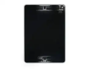
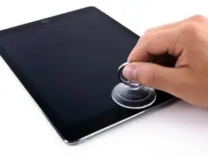
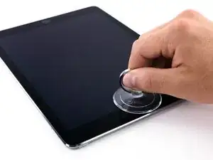
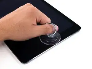
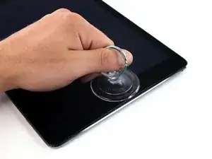
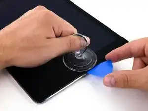
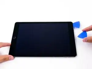
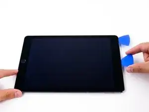
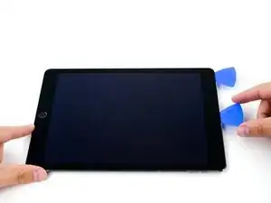
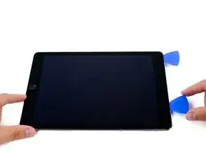
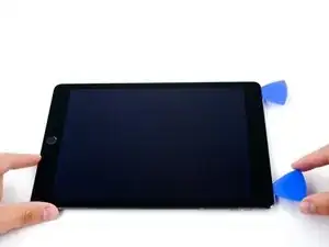
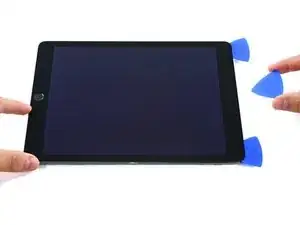
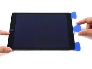
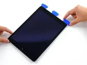
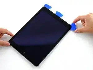
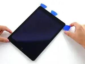
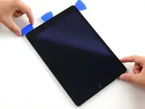
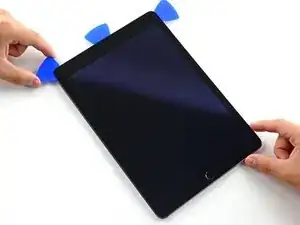
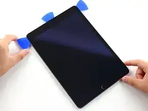
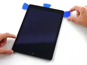
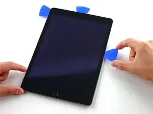
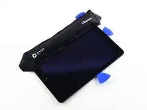
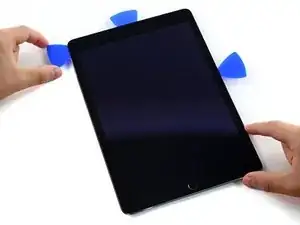
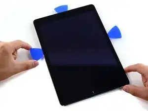
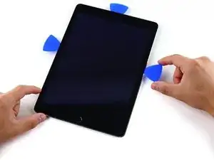
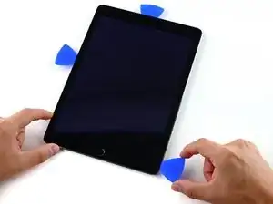
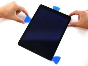
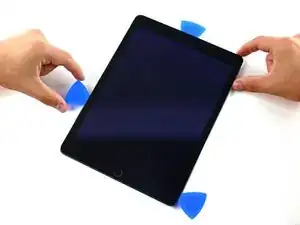
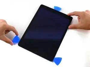
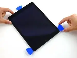
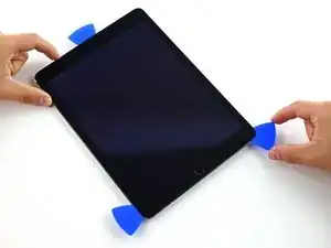
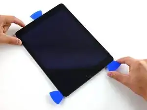
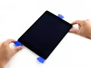
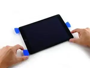
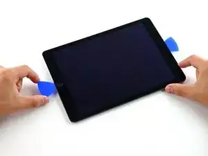
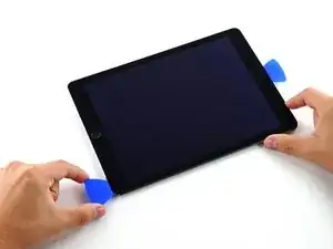
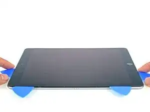
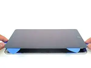
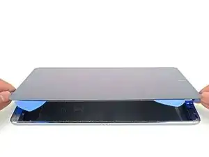
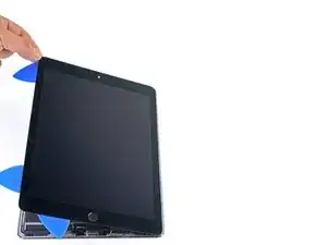
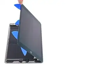
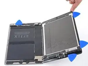
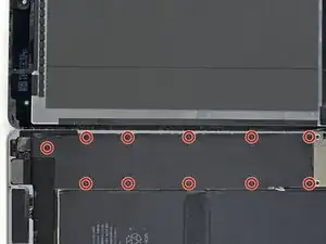
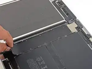
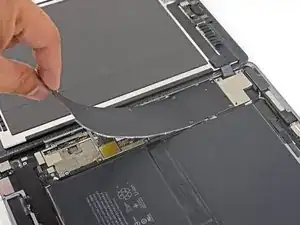
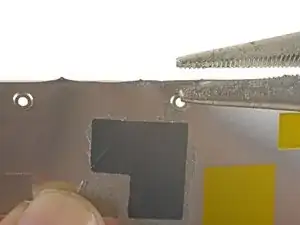
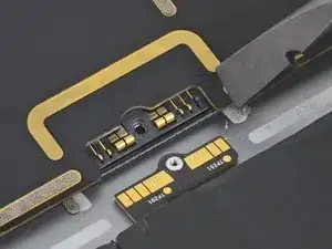
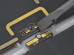
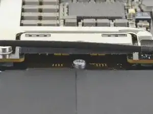
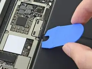
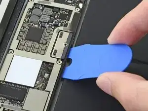
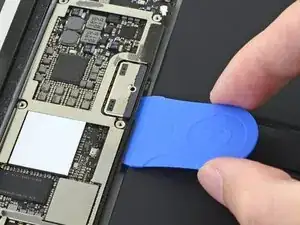
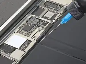
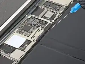
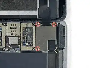
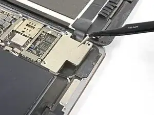
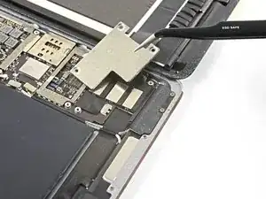
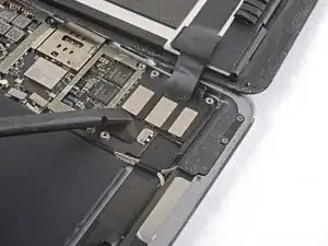
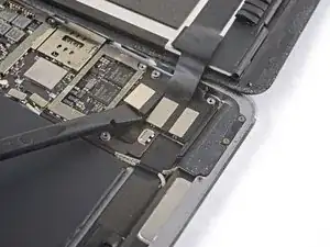
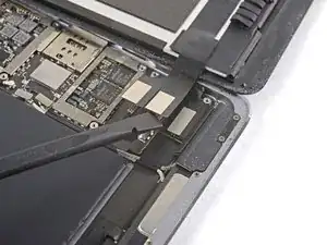
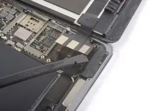
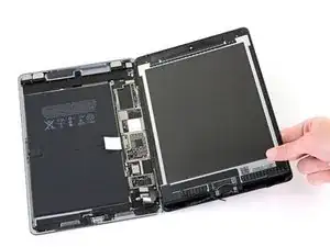
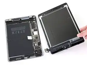
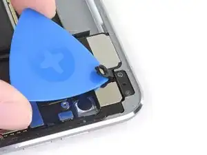
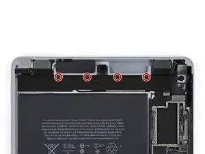
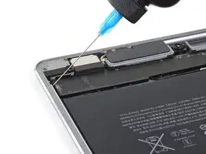
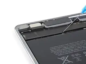
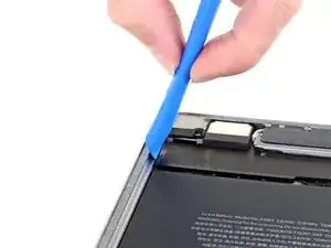
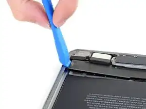
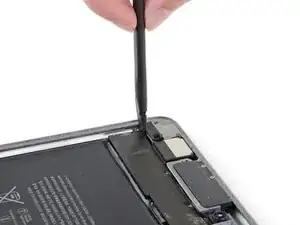
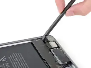
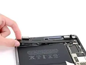
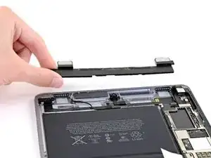
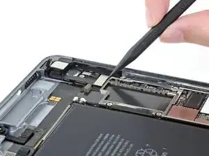
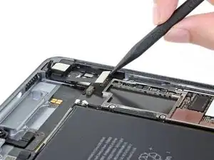
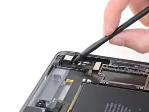
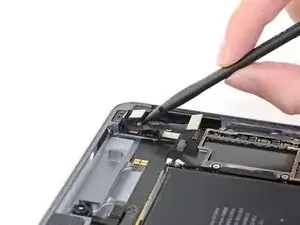
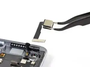
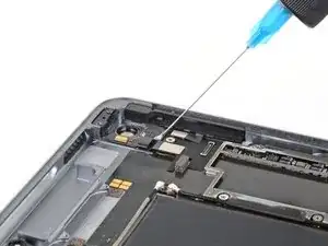
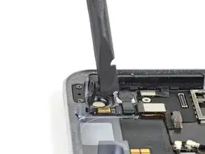
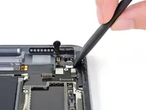
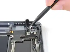
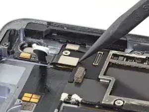
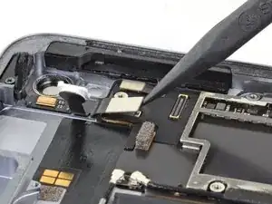
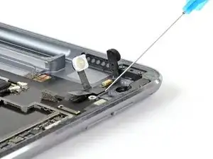
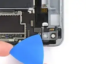
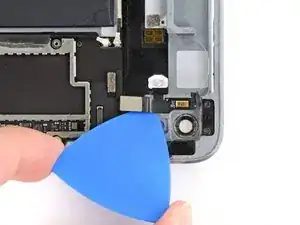
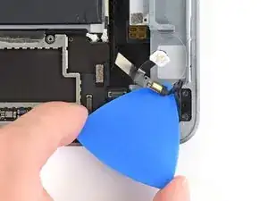
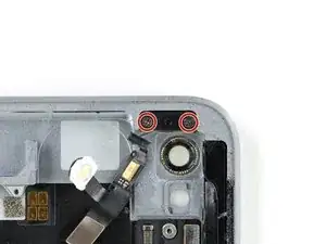
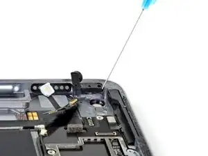
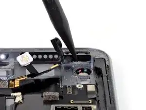
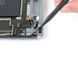
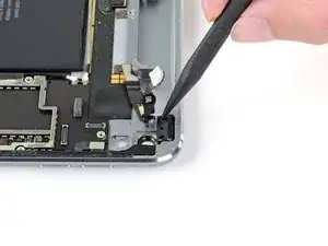
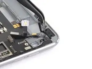
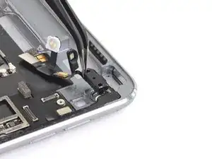
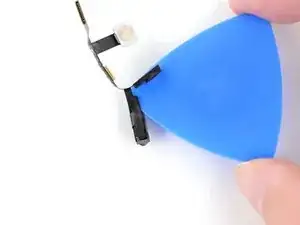
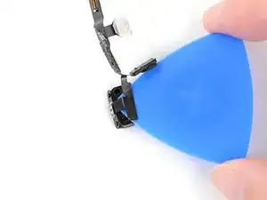
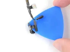
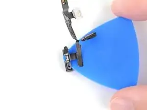
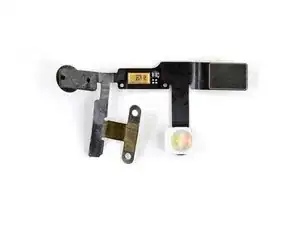
Follow this guide to remove or replace the power button assembly on an iPad Pro 9.7".

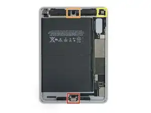
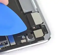
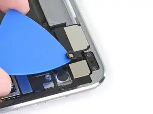
The power button assembly includes one of two microphones, one of two ambient light sensors, the flash, and the internal power button switch for the iPad Pro 9.7". You may need to replace the power button assembly if any of these components stop working.

Note that this guide is for replacing the internal power button cable and switch assembly, not the external power button face.

For your safety, discharge the battery below 25% before disassembling your device. This reduces the risk of a dangerous thermal event if the battery is accidentally damaged during the repair. If your battery is swollen, take appropriate precautions.

Some photos in this guide are from a different model and may contain slight visual discrepancies, but they won't affect the guide procedure.

  1. 4fSrpT12RPOorLqZ
    4fSrpT12RPOorLqZ
    YEXM13x4vxQLEIqa
    CUUZal13vZyLAeHH
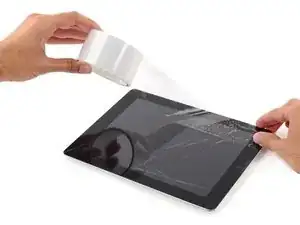
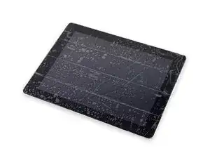
    • If your display glass is cracked, keep further breakage contained and prevent bodily harm during your repair by taping the glass.

    • Lay overlapping strips of clear packing tape over the iPad's display until the whole face is covered.

    • This will keep glass shards contained and provide structural integrity when prying and lifting the display.

    • Do your best to follow the rest of the guide as described. However, once the glass is broken, it will likely continue to crack as you work, and you may need to use a metal prying tool to scoop the glass out.

    • Wear safety glasses to protect your eyes, and be careful not to damage the LCD screen.

    Covering the screen with tape proved an essential safety step with the ipad display/lcd I just replaced. The screen was so badly broken that a part of it was almost powder, but the combination of the tape and sticky adhesive residue kept most of that together, and cleanup was pretty easy as a result. One caveat, though, is that the tape will probably make the suction cup useless for pulling up on the display. It did for me, anyway.

    John Lasseter -

  2. r4amr5F6MjBUIQnt
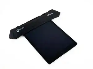
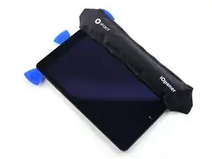
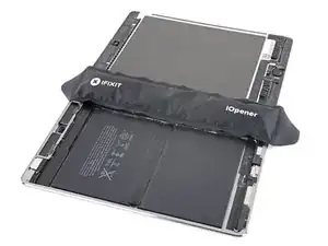
    • The following steps involve using an iOpener to soften the adhesive holding the front panel assembly in place. When using the iOpener, be sure to heat it in the microwave for no more than 30 seconds.

    • Handling it by the tabs on either end, place a heated iOpener over the top edge of the iPad.

    • Let the iOpener sit on the iPad for two minutes to soften the adhesive securing the front panel to the rest of the iPad.

    I see a lot of videos that show using a heat gun on low to soften the adhesive. I know there is inherent risk with this since you could start delaminating things, but is it something that could be considered (at your own risk)? Or is it something that could have more risks than I am realizing?

    joshcorey -

    Yes, you can definitely use a hair dryer, heat gun, or a heating pad. If you're using a heat gun, be careful not to overheat the display. The surface should feel slightly too hot to the touch.

    Arthur Shi -

  3. vbug1VOBMObXrrNJ
    vbug1VOBMObXrrNJ
    lM2svovREMXARVPx
    QQCvcb1RJlUkbUQW
    • While the iPad looks uniform from the outside, there are delicate components under certain portions of the front glass. To avoid damage, only heat and pry in the areas described in each step.

    • As you follow the directions, take special care to avoid prying in the following areas:

    • Home Button

    • Front Facing Camera

    • Main Camera

    Verwirrend: Es sollte heissen, dass man an den beschriebenen Stellen eben NICHT hebeln sollte.

    Felix -

    Danke! Ich habe den Teil mit dem NICHT hebeln nochmal hervorgehoben.

    Fabian Neidhardt -

    The screen cable is on the right side at the bottom. Be super careful not to slice too deeply there

    Gerald -

  4. KNVk2a1AUMciEshg
    KNVk2a1AUMciEshg
    cFIoQKTkU2nO5tfW
    ciSmehC6fBvHFjKR
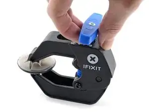
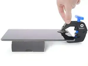
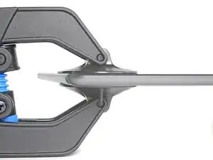
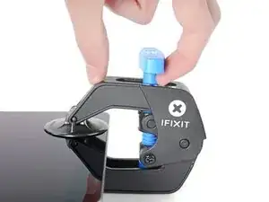
    • The next two steps demonstrate the Anti-Clamp, a tool we designed to make the opening procedure easier. If you aren't using the Anti-Clamp, skip down two steps for an alternate method.

    • For complete instructions on how to use the Anti-Clamp, check out this guide.

    • Elevate the iPad enough for the Anti-Clamp's arms to rest above and below the screen.

    • Pull the blue handle towards the hinge to disengage opening mode.

    • Position the suction cups near the top edge of the iPad—one on the front, and one on the back.

    • Push down on the cups to apply suction to the desired area.

    • If you find that the surface of your device is too slippery for the Anti-Clamp to hold onto, you can use packing tape to create a grippier surface.

  5. f1wKrgiJGt1qr2KD
    f1wKrgiJGt1qr2KD
    duPJTFGfLCfRIlTF
    jItC1msuNMKW5yOH
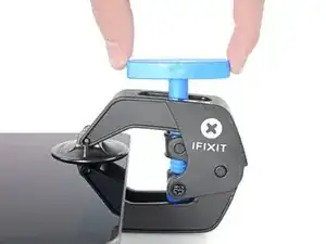
    • Push the blue handle away from the hinge to engage opening mode.

    • Turn the handle clockwise until you see the cups start to stretch.

    • Make sure the suction cups remain aligned to each other. If they begin to slip out of alignment, loosen the suction cups slightly and realign the arms.

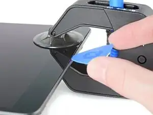
    • Wait one minute to give the adhesive a chance to release and present an opening gap.

    • Insert an opening pick under the screen when the Anti-Clamp creates a large enough gap.

    • If the Anti-Clamp doesn't create a sufficient gap, apply more heat to the area and rotate the handle clockwise half a turn.

    • Don't crank more than a half a turn at a time, and wait one minute between turns. Let the Anti-Clamp and time do the work for you.

    • Skip the next two steps.

    Do not use the anti clamp beyond this step. Doing so will run the risk of putting pressure on the screen and cracking it. Only use it for the initial opening of the device.

    Playincrzy -

  6. rpaBWg5X1LUnivHt
    rpaBWg5X1LUnivHt
    NXKEJYkJ5HpXf5cV
    • Place a suction cup over the iPad's front-facing camera and press down to create a seal.

    • To get the most leverage, place the suction cup as close to the edge as possible without going past the edge of the display.

  7. mJCqfjEDtJeihiXC
    mJCqfjEDtJeihiXC
    LhCLCjtgwcD4eQVo
    nZkUghUs1xfKEWTf
    • Firmly pull up on the suction cup to create a small gap between the front panel and the rear case.

    • Do not pull too hard or you may shatter the glass.

    • Once you've opened a sufficient gap, insert an opening pick into the gap to prevent the adhesive from resealing.

  8. UBZTHwdRqbwRLJAl
    UBZTHwdRqbwRLJAl
    RTJrYjnQCiMxQGEw
    4TraNDygnvQCXDJV
    • Slide the pick along the edge of the display, towards the headphone jack.

    • If there is still a considerable amount of resistance when sliding the opening pick, repeat the iOpener heating procedure and apply additional heat.

    • Don't insert the pick past the bezel into the display area, or you will damage it.

    • A good rule of thumb is to never insert the opening pick more than a quarter inch into the iPad.

  9. y34OmvNZddjUsgJf
    y34OmvNZddjUsgJf
    dKyTUwZlqudvsrwS
    • Insert a second opening pick by the front-facing camera.

  10. VlouIlKDBobp21ht
    VlouIlKDBobp21ht
    4D3HnAB5lW6NWtQP
    usBnHAdBOnUhgKgZ
    • Slide the second pick along the top edge of the iPad, towards the Sleep/Wake Button.

  11. QItKpaRbXb1UvjCF
    QItKpaRbXb1UvjCF
    GWdnFUu2a2WqNBRk
    • Insert a third pick by the front-facing camera.

  12. SB6QxHsLajVvHKLF
    SB6QxHsLajVvHKLF
    6jAjQvNWJtPA1icQ
    bfWiL6JjqPuCHktD
    • Bring the right opening pick down and around the top right corner of the iPad.

  13. iEwCprM5hUbjMa5M
    iEwCprM5hUbjMa5M
    btBkuNsD1BGWdmNi
    ZeLYciNptnjMD5sN
    • Bring the left opening pick around the top left corner of the tablet.

  14. fpXSlsGA4PuXZwtC
    • Reheat the iOpener and lay it over the right edge of the display to loosen the adhesive underneath.

  15. bYJQLgFB46cU2pVJ
    bYJQLgFB46cU2pVJ
    bZDFr4X45b4DahBn
    s1wTnCHfVesRTpQu
    • Slide the right opening pick roughly halfway down the display.

  16. JMuZWuybr3UclCyZ
    • Reheat the iOpener and apply heat to the left side of the iPad.

  17. IQRxoNTBSGtLM3i2
    IQRxoNTBSGtLM3i2
    ETnV2UuToukcU3om
    jJatPsp4QkC3AahX
    • Slide the left-hand opening pick about halfway down the edge of the display.

  18. GReHqx2PqZURrOmS
    GReHqx2PqZURrOmS
    EKxY1RGlSXtPGpwj
    QoZPMgkyQQwPXR6j
    • Slide the opposite opening pick down to the bottom right corner of the iPad.

    • If necessary, reheat the adhesive on the right edge to loosen the display assembly.

    The screen cable is on the right side at the bottom. Be super careful not to slice too deeply there

    Gerald -

  19. wwPbdKhkSwI5hQMG
    wwPbdKhkSwI5hQMG
    LaZr2wpWCByppuVW
    UIXuRBEr3LiC3Bhm
    • Slide the left-hand opening pick down the edge of the display until you reach the corner.

    The screen cable is on the right side at the bottom. Be super careful not to slice too deeply there

    Gerald -

  20. UsPELiDHRgD5GTqy
    • Use the iOpener to apply heat to the bottom edge of the iPad.

  21. wygPNSUXUUeMhjok
    wygPNSUXUUeMhjok
    YmJCAGY5oke2TUDU
    IlKVDslEYyMPKjBL
    • Bring the right-hand opening pick around the bottom corner of the iPad.

  22. xfVKIvrVyEGfeDkD
    xfVKIvrVyEGfeDkD
    3RsbTJPXwtVsrU5J
    2yL1bOTG6QjYfuw1
    • Repeat for the left-hand pick.

    • Reheat and reapply the iOpener as needed.

  23. IUNdFVqTQHS6UKiG
    IUNdFVqTQHS6UKiG
    h1UtPwFlqFxDEvCB
    • Remove the right-hand opening pick at the bottom of the iPad.

  24. XSUmMZChFquPbMVK
    XSUmMZChFquPbMVK
    BRuNiWvEDx3xpiaU
    G4mFOROitEkXfpcQ
    • Slide the left-hand opening pick along the bottom edge of the display, then remove it from the bottom right corner of the iPad.

    • Be very careful to not insert the pick more than a quarter inch into the display to avoid damaging the Home Button and display cables underneath.

  25. UMABNUvs1JAY5CnQ
    UMABNUvs1JAY5CnQ
    pjKHFWXeNHKb1Fwn
    n5dLBWCNCLviV3tO
    • Use picks to ensure most of the adhesive has been cut through on the top, left, and bottom sides.

    • Twist the top and bottom picks to separate the display assembly from the rear case.

    • Do not attempt to remove the display—it is still attached to the rear case.

  26. EUHYHMoMYHmZQtDe
    EUHYHMoMYHmZQtDe
    3Jrxx2QT1hOKvYfK
    QPswhfhlMOBus4Xt
    • Swing the display assembly towards the right of the case, using the right edge as a hinge.

    • As you move the display assembly, make sure that the display ribbon cable is not being stressed.

    • Continue swinging the display assembly until it lays flat next to the rear case.

  27. OmKcSXAUbgvGwQDa
    • Use a Phillips screwdriver to remove the eleven 1.3 mm screws securing the EMI shield.

  28. pmOYYDEugngE3r5u
    • Apply a heated iOpener to the EMI shield on the logic board for one minute.

  29. e1sL5f4ExNuJAext
    e1sL5f4ExNuJAext
    QiJq5COIviJNFLjS
    2IYWhakABvD1ZxOE
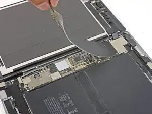
    • Lift the logic board EMI shield, starting at the edge nearest the top of the iPad.

    • Slowly peel the EMI shield up from the logic board.

    • This takes a bit of force due to the many tiny clips securing the shield, and the shield may deform slightly. That's okay—try to keep the deformation to a minimum, and it will lay flat when reinstalled and screwed down.

    • Remove the logic board EMI shield.

    Don't peel the cover as shown from a short side. Lift the long side to avoid creasing the cover so much. This way it will lie flat when you reassemble it and not look so ugly. Also, you won't have to straighten so many creases with pliers

    Jim Meyers -

  30. D6aqtQGXLmCYbHBt
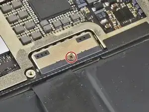
    • Use a Phillips driver to remove the 1.7 mm-long screw securing the battery connector.

    What size is this screw?

    Austin Martin -

    i get 1.65mm with my calipers but the 1.3s read 1.25 on my calipers too, so probably a 1.7mm

    bunjamins -

  31. yQVBO6oOKlNeidgA
    yQVBO6oOKlNeidgA
    WNbapGR1pFsKRftp
    pg232afeScFRxNik
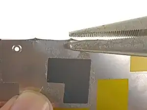
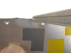
    • If the EMI shield has any sharp protrusions after removal, you should flatten them before reinstalling the shield.

    • Squeeze the sharp protrusion with a pair of pliers to flatten it.

    • Repeat the process for all sharp protrusions along the edges of the EMI shield.

    Don't peel the cover as shown from a short side. Lift the long side to avoid creasing the cover so much. This way it will lie flat when you reassemble it and not look so ugly.

    Jim Meyers -

  32. XpIgLlSVJMdt4NyP
    XpIgLlSVJMdt4NyP
    V1V2DyoEgl4mTn6v
    yL3XcWjTZ5XaXsLf
    • These photos show what the battery connector looks like underneath the logic board. Use these photos as a reference while you safely disconnect the battery.

    • Notice that the battery connector has cantilever springs on the logic board that press against the battery contact pads. Since both the logic board and battery are glued down, you'll need to slide something thin and flexible between the contact points to disconnect the battery.

    Le connecteur de batterie est il réparable si abîmé ?

    Maverick -

  33. ydsWDNC5XgN5TGkA
    ydsWDNC5XgN5TGkA
    lYxVPnwP1yejWAfd
    QgNCDMbA2bNqcQio
    • Be careful when you isolate the battery using a battery blocker. The battery contacts are easily bent or broken, resulting in irreversible damage.

    • Ensure that the iFixit logo on the battery blocker is facing up.

    • Slide the battery blocker underneath the left side of the logic board's battery connector at a 35 degree angle.

    • The battery blocker's right prong should slide between the left side of the logic board's battery connector and the battery's contact pads. The left prong should slide under the logic board.

    • Don't push the battery blocker underneath the connector or logic board with excessive force. If you're having trouble fitting the battery blocker underneath the logic board, refer to the next step for information on loosening the logic board. You can also try using a playing card to disconnect the battery instead.

    • The battery blocker or playing card should slide under the logic board without encountering any blockages. After insertion, they should rest at a 15 degree angle.

    • Leave the battery blocker in place as you work.

    le connecteur de la batterie est t’il remplaçable ou repérable si jamais abîmé ?

    Maverick -

  34. GNruVZHL1TYb2igd
    GNruVZHL1TYb2igd
    xlWNIlPRyuIaf3DP
    • If the battery blocker doesn't easily slide under the logic board, follow these steps to partially loosen the logic board from the frame:

    • Apply a few drops of high-concentration (90% or higher) isopropyl alcohol under the logic board to the left and right of the battery connection.

    • Wait one minute for the isopropyl alcohol to weaken the adhesive under the logic board.

    • Try to insert the battery blocker. If the logic board doesn't easily lift up, apply a few more drops of isopropyl alcohol.

    • This doesn't apply when using the playing card method to disconnect the battery because the playing card is only inserted between the battery connector and the battery contact pads.

  35. SSnJJGWG4QmSor5T
    • Use a Phillips screwdriver to remove the three 1.3 mm Phillips screws securing the display cable bracket.

    i think we need to talk about the battery situation here. apple change up the style of battery connector on this model as well as some others. if someone can add to this list and add the appropriate photos in the right spot should help someone else. the battery tabs are open towards the battery side and inserting a tool in this area can pry them open further and damage or rip off the tab. some have found that by lifting on either side of the battery tab, they would not even encounter the tabs.

    greg -

  36. 1a4ywPCBXTXe1uPJ
    1a4ywPCBXTXe1uPJ
    NQOaPfW4OXpa5vek
    • Remove the display cable bracket.

    A tab was folded over a connector of some sort on the bottom side. I found it was a better to pull from the top to the bottom to fold the tabs slightly to remove this cover.

    rosecitymech -

    Actually it helps to move the cover slightly towards the bottom of the iPad as that disengages to tabs…

    DeeAnn Hopings -

  37. N3WqLqmlprqjmhha
    N3WqLqmlprqjmhha
    vyNRHkW1HFHRt5rb
    • Use the flat end of the spudger to disconnect the display assembly connector from the motherboard socket.

  38. 6ym1twSljAhoSG46
    6ym1twSljAhoSG46
    FMHLJUerOdlvCIJh
    • Repeat the previous step for the two remaining connectors.

  39. VfYWrFtvNprHjYIC
    VfYWrFtvNprHjYIC
    C5LVpSEBGFwHVbQb

    You "CAN" skip steps 41 through 98 and 102-109 if you're confident in your repair abilities and PATIENT. Lots of alcohol around all the edges of the battery, and apply heat to the back cover on one half of the battery, the slowly ease your "card under the edges of the battery. Wiggle it back and forth and add more alcohol under the edges of the battery where your working; DONT PUSH your card to hard or you will sli[p and damage components. Then do the same for the other half. When both halves are loose, fold over one end and slide the flat edge off the spudger under the area of the logic board next to the battery connector, then do the same to the other side; you want just enough of a gap under the logic board to lift the battery tab off of the post then you can remove the battery.

    Gregg Stanley -

    ディスプレイアッセンブリを外して、黒くて古い接着テープをはがしすためにぴっぱったら、ディスプレイと本体基盤を接続するコネクターのテーブを不注意で切断してしまった。これで、交換はあきらめで中止。注意されたし。ちなみに、手順41~89は省いてもバッテリー交換ができるのではないかと思います。

    susuper -

  40. IYUFLXxOeLlihujU
    IYUFLXxOeLlihujU
    MJUUPnyjP6NRxmub
    wBLG3cpWIXHSr5yh
    • Slide an opening pick under the right ambient light sensor to loosen its adhesive.

    • There are two pegs on the shelf that position the ambient light sensor—one on the bottom edge and one near the top edge.

    The "right ambient light sensor" can be replaced?

    If yes, where can I find the replacement part?

    Michael Rodriguez -

    The light sensor has a rubber collar. If you lift the cover you can see a tiny peg pushed upwards onto the bottom of the sensor base. It’s the base you need to lift and it is stuck down

    Gerald -

  41. 5HkHHPpUTEjqcUCE
    • Use a Phillips screwdriver to remove the four 1.9 mm-long screws securing the upper speaker to the frame.

  42. Cm14Q1sUYtyQpVMC
    Cm14Q1sUYtyQpVMC
    nBjRvDVtvBU2KnI3
    • Strong adhesive secures the upper speaker to the frame.

    • Apply a few drops of high-concentration (90% or higher) isopropyl alcohol under the upper speaker.

    • Wait one minute for the isopropyl alcohol to weaken the adhesive under the upper speaker.

  43. pMBIkLrgnjqVAWAl
    pMBIkLrgnjqVAWAl
    QvQ16GyiAXRDAPBY
    • Use an opening tool to pry up the left edge of the upper speaker.

    • Try to avoid bending the upper speaker while prying it up. Some bending will likely happen during this process, but excessive bending may damage the upper speaker.

    • If the upper speaker isn't detaching from the frame, apply a few more drops of isopropyl alcohol.

    These next 3 steps are the most difficult of the whole process. The speaker is glued down along its whole length which must all be freed. Use the iopener underneath the top of the iPad whilst you are waiting for the alcohol to work to help soften the glue.

    On the left hand side, there is a flat cable glued to the back plate and the speaker is then glued on top of the cable. So when you put the alcohol down it’s most likely to deboned the cable which will remain attached to the speaker as you lever it up and need carefully separating somehow.

    There is a zif connector on that cable underneath the speaker and just to the left of the front facing camera so there’s not much play. If you are unable to remove cable from the bottom of the speaker, you’ll pull the cable out of the connector as you lift the speaker. Don’t lever the speaker downwards (next step) until this zif connector is detached or you’re trash the connector itself.

    There’s also a round wire which passes underneath the speaker, that’s a bit stronger.

    Gerald -

  44. uHMlbQnjXYxWDGyL
    uHMlbQnjXYxWDGyL
    46DsylclyRAAdRyj
    • Use the flat end of a spudger to push the left side of the upper speaker toward the battery just enough for the left speaker to slide out of its recess in the frame.

    The external speaker (headphone socket) on the left side of the speaker must be removed. 2 screws for the cover, 1 for the socket support. As well as a sensor of some sort. The cover for the sensor came off separately.

    Rogie B -

    I didn’t remove that speaker but doing so may give to more access to lift the speaker unit upwards.

    DO NOT move the speaker downwards until you have completely separated the speaker from the flat cable glued to the bottom of it on the left hand side or disconnected the zif connector. See my comment in previous step.

    Gerald -

  45. YSR3WaZTCiSvcSlA
    YSR3WaZTCiSvcSlA
    i2TYt2QoPvPZVL6Y
    • Lift and remove the upper speaker from the frame.

    • There are multiple cables under the upper speaker. Be careful not to damage them while removing it.

    • If any cables are still attached to the upper speaker while you lift it up, carefully peel them off of the upper speaker. You can apply more isopropyl alcohol if they don't easily peel away.

    • If the ZIF connector sticker near the front camera comes off while removing the upper speaker, reapply it to the ZIF connector.

    • If the ZIF connector near the front camera disconnects while removing the upper speaker, use the pointed end of a spudger to flip up the locking flap. Then, reinsert the ribbon cable and close the locking flap.

    • During reassembly, make sure the right ambient light sensor is on top of its shelf.

    • If there's any alcohol solution remaining in the device, carefully wipe it off or allow it to air dry before reinstalling the upper speaker.

    You are going to disconnect the zif connector later. If it’s popped out there’s not need to put it back.

    Gerald -

  46. GncxVc4UimSrDwoO
    GncxVc4UimSrDwoO
    5YJxG361uQVUwpMY
    • Use the pointed end of a spudger to disconnect the rear camera's press connector from its socket.

    • Be careful to pry only under the edge of the connector, and not under the socket itself. If you pry under the socket, you will separate it from the circuit board.

    • To reconnect, align the connector carefully over its socket and press down with your fingertip—first at one side, then the other—until it clicks into place.

    • Do not press down on the middle until the connector is fully seated—if it's misaligned, the connector can bend, causing permanent damage.

  47. I5iGtQMyc6EAL1Qa
    I5iGtQMyc6EAL1Qa
    OhucZSAuEwF3eWIK
    • Insert the flat end of a spudger under the bottom edge of the rear camera and pry up to detach it from the frame.

    • If it doesn't detach from the frame when you pry up, apply a few drops of high-concentration (90% or higher) isopropyl alcohol to the perimeter of the rear camera. Wait thirty seconds for the isopropyl alcohol to weaken the adhesive.

    • If you're going to reuse the rear camera, don't use an excessive amount of isopropyl alcohol and don't get any on the camera lens. Isopropyl alcohol on the lens may cause permanently foggy photos.

  48. Ib66vfTMXpcEA6FR
    • Use a pair of tweezers to remove the rear camera.

    • If you plan to reuse the rear camera, be careful not to scratch the lens.

    • If there's any alcohol solution remaining in the device, carefully wipe it off or allow it to air dry before installing your rear camera.

    • During reassembly, follow this guide if you are using a pre-cut adhesive card to secure the rear camera to the frame.

  49. l3VoSTJmGvlgrtIF
    • Apply a few drops of high-concentration isopropyl alcohol to all four corners of the flash.

    • Wait thirty seconds for the isopropyl alcohol to weaken the adhesive securing the flash to the frame.

  50. JueiCuos4hsCKym4
    • Use the flat end of a spudger to scrape away the adhesive on the flash.

    • If any particles fall onto the camera cover, remove them with a lint-free cloth.

  51. VEKYLjWn2BSrqrf3
    VEKYLjWn2BSrqrf3
    BAEH6R2myHX6dOIK
    • Use the flat end of a spudger to lift the flash out of its recess.

    • The flash should lift out easily when enough adhesive has been removed.

    • During reassembly, apply pre-cut adhesive to all four corners of the flash to secure it to the frame.

  52. FUcgCLgqCTtHFBNg
    FUcgCLgqCTtHFBNg
    pNbOJXyIUKZySZiU
    • Use the pointed end of a spudger to disconnect the power button assembly's press connector from its socket.

  53. xOomfHbVQYOCQZHU
    • Apply a few drops of high-concentration isopropyl alcohol to the edges of the power button cable.

    • Wait thirty seconds for the isopropyl alcohol to weaken the adhesive under the power button cable.

  54. aPso2VGVFTwvyTYn
    aPso2VGVFTwvyTYn
    fpDSf2vFIIt65hNc
    qUcSOb3fuhFrEieH
    • Use an opening pick to cut through the adhesive under the power button cable.

    • During reassembly, apply pre-cut adhesive under the power button cable to secure it.

    • Make sure the power button cable's press connector lines up with its socket before fully applying the pre-cut adhesive.

  55. EH2sKMYQ41lHD3j6
    • Use a Phillips screwdriver to remove the two 4.4 mm-long screws securing the power button bracket to the frame.

  56. aRNcR5usmx2bt1Dn
    • Apply a few drops of high-concentration isopropyl alcohol to the adhesive securing the power button bracket to the frame.

    • Wait thirty seconds for the isopropyl alcohol to weaken the adhesive.

  57. 6PJm54jMWFQlhccc
    • Use the pointed end of a spudger to scrape away the adhesive on the bottom edge of the power button bracket.

    • If any particles fall onto the camera cover, remove them with a lint-free cloth.

  58. xrB4ptKe3AIHMUcB
    xrB4ptKe3AIHMUcB
    JQSQQDxdf1rYM6ek
    • Insert the pointed end of a spudger into the left screw hole on the power button bracket.

    • Push the power button bracket out of its recess.

  59. GNMQeQQ4TA6w1VYs
    GNMQeQQ4TA6w1VYs
    R5Wrg5DfEFxurWLB
    • Use a pair of tweezers to remove the power button bracket.

  60. fqyDCsjMdUSwwUYB
    fqyDCsjMdUSwwUYB
    6SISWFlkacdKosZP
    • Use an opening pick to cut through the adhesive securing the power button cable to the power button bracket.

  61. 1RhbZllFQKae3uCV
    1RhbZllFQKae3uCV
    FrnWG5GORSUUjNVb
    • Continue to cut through the adhesive until the power button assembly completely detaches from the power button bracket.

  62. yBcrj5IlRoKihNsE
    yBcrj5IlRoKihNsE
    iBThkVONUC3ImaWI
    • Only the power button assembly remains.

    • If your replacement power button assembly doesn't come with a power button bracket, you'll need to reuse the original bracket.

    • Use a pair of tweezers to remove any leftover adhesive on the power button bracket.

    • Apply pre-cut adhesive to secure the power button cable to the power button bracket.

    • Make sure to align the power button cable's holes with the two pegs on the power button bracket to ensure a proper fit.

    • If there's any alcohol solution remaining in the device, carefully wipe it off or allow it to air dry before installing your power button assembly.

Conclusion

Compare your new replacement part to the original part—you may need to transfer remaining components or remove adhesive backings from the new part before installing.

To reassemble your device, follow these instructions in reverse order.

Take your e-waste to an R2 or e-Stewards certified recycler.

Repair didn’t go as planned? Try some basic troubleshooting, or ask our iPad Pro 9.7" Answers community for help.
Kyle Smith

Member since: 01/02/21

43003 Reputation

0 comments