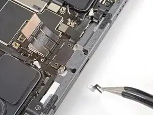
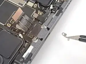
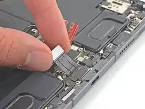
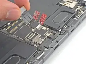
Introduction

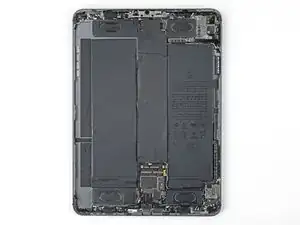
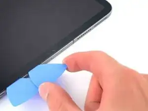
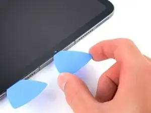
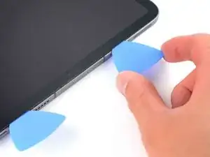
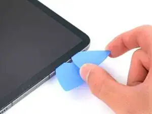
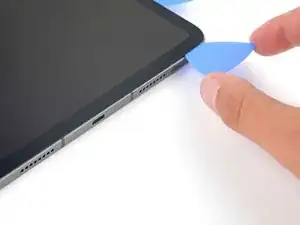
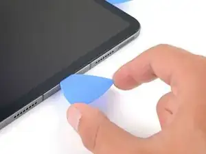
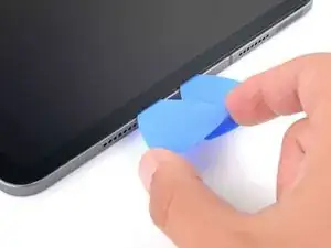
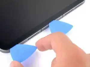
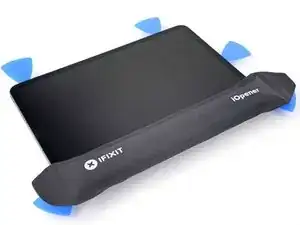
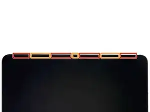
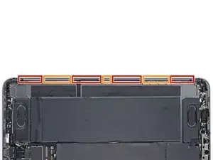
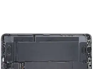
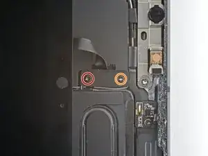
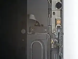
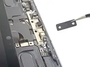
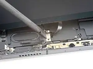
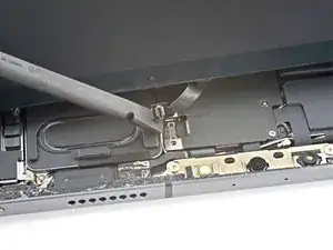
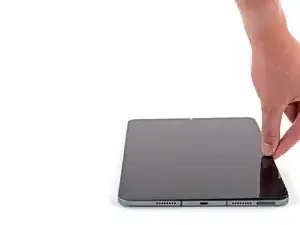
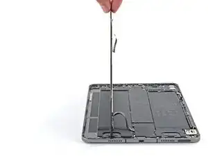
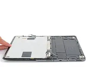
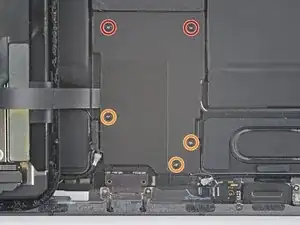
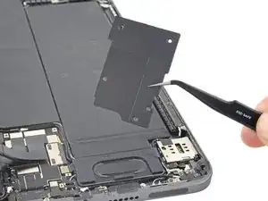
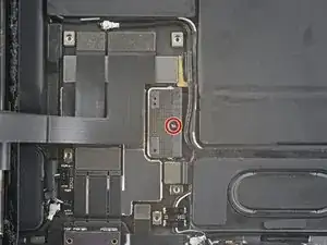
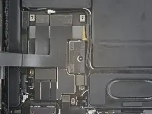
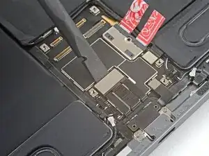
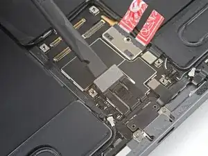
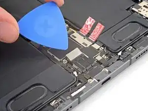
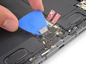
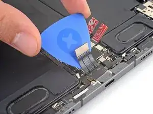
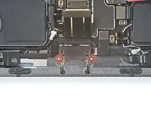
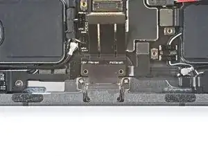
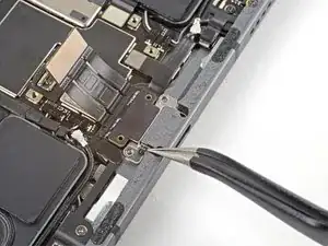
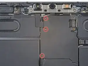
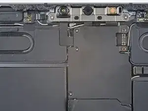
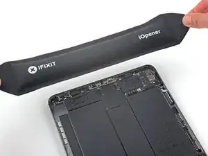
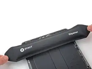
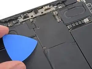
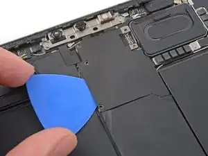
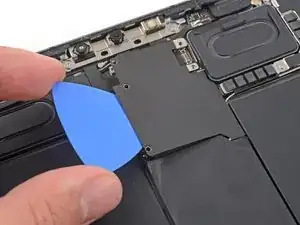
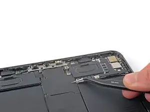
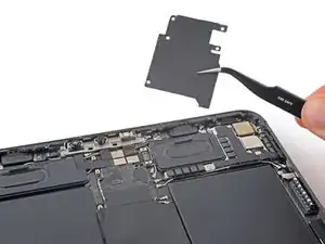
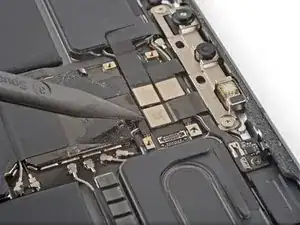
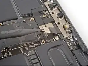
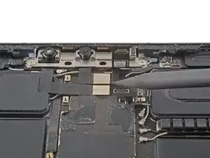
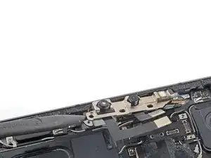
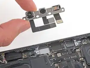
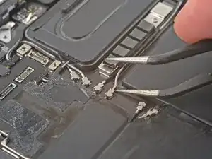
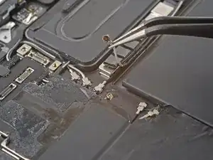
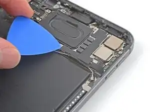
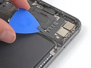
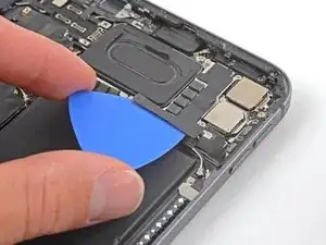
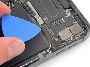
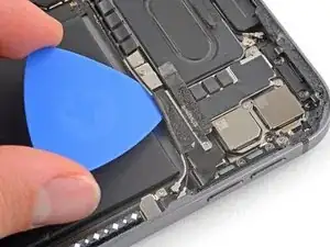
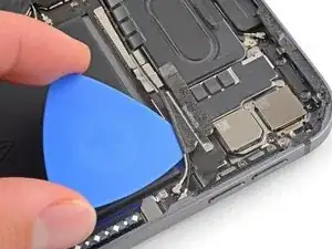
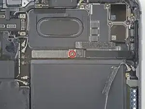
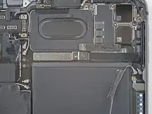
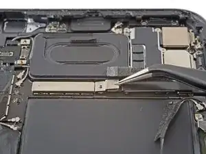
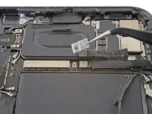
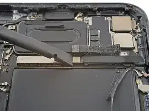
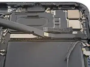
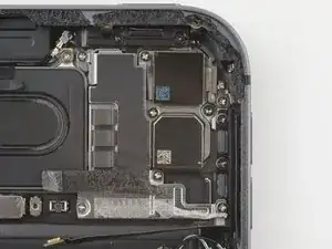
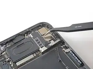
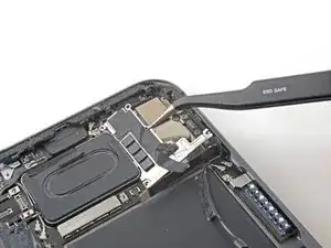
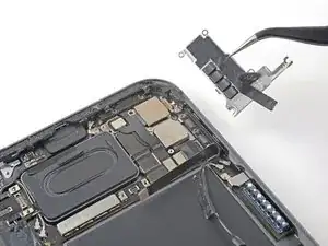
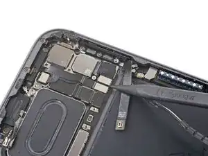
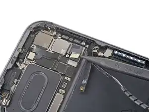
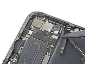
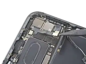
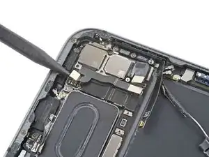
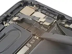
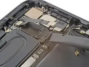
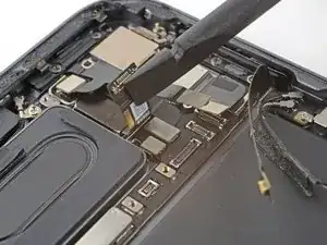
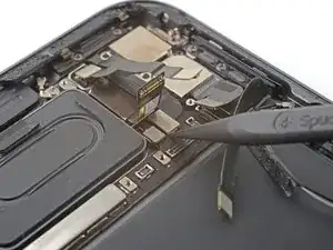
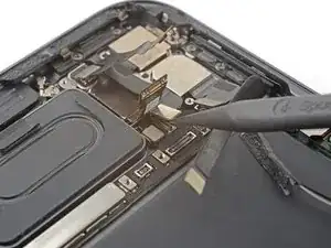
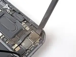
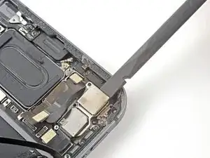
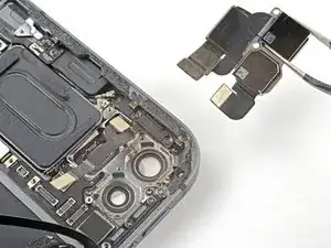
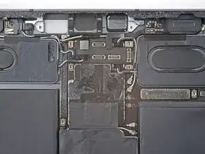
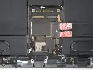
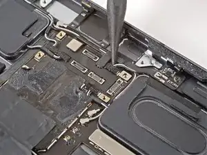
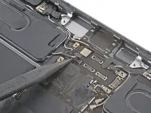
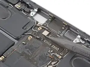
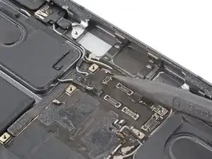
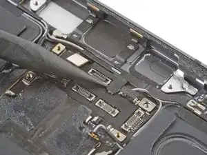
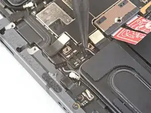
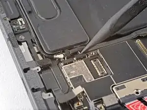
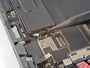
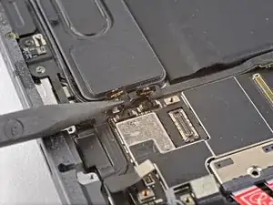
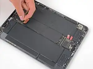
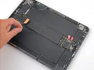
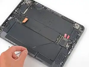
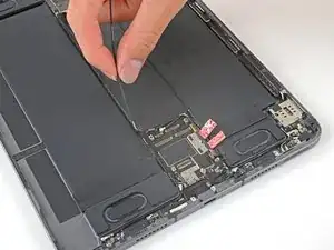
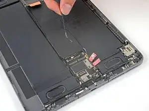
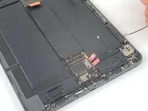
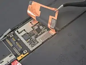
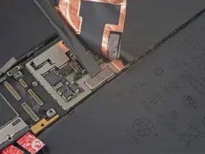
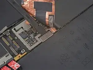
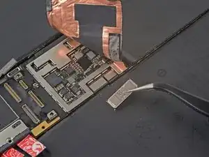
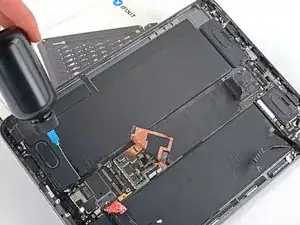
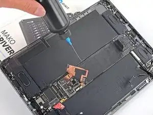
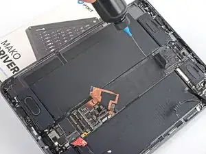
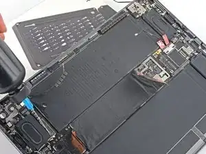
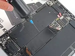
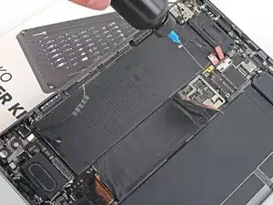
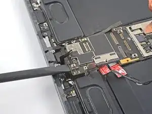
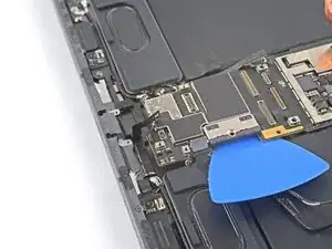
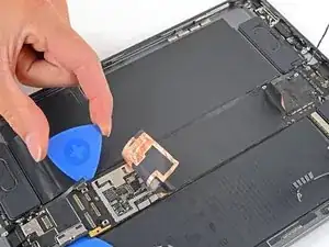
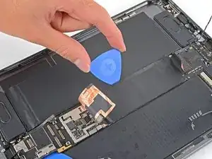
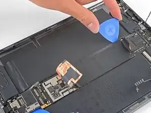
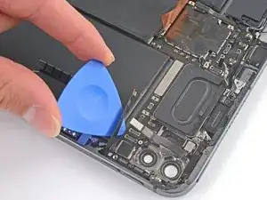
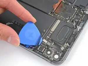
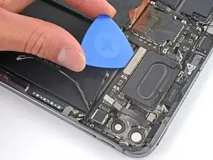
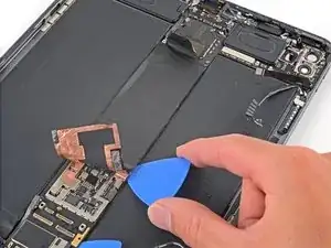
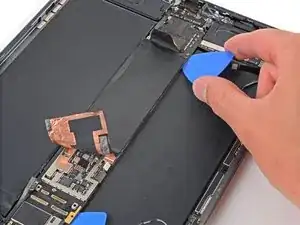
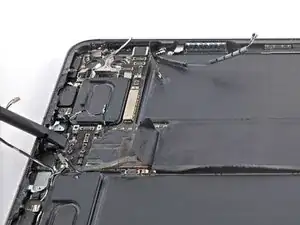
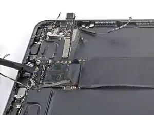
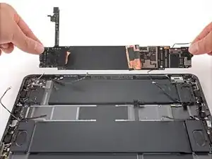
Follow this guide to replace the logic board in your iPad Pro 11" 3rd gen.

The logic board in your iPad Pro is paired to the Face ID hardware. Replacing it will disable Face ID.

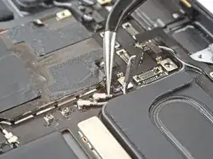
This guide is written with an A2301 (cellular + mmWave) model iPad Pro. If you're fixing a Wi-Fi model, you can still use this guide—there will be some visual discrepancies, and you'll need to skip the steps related to the cellular antennas.

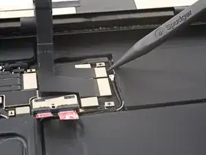
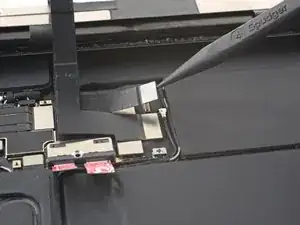
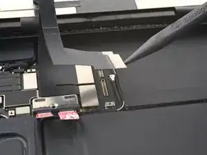
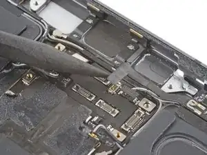
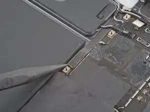
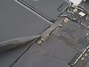
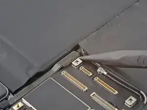
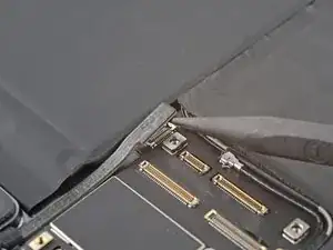
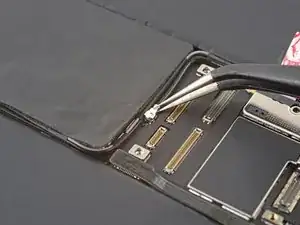
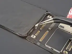
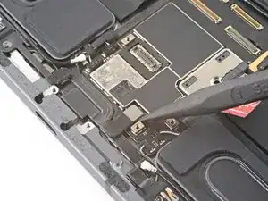
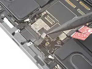
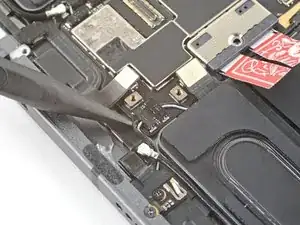
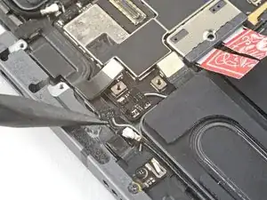
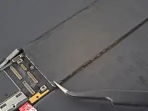
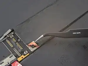
Some photos show the battery connector blocked with two card strips. While this is an optional method, it's more reliable to fully discharge the battery. Ignore this visual discrepancy as you work through the guide.

  1. YWVxO1movQWwpRq4
    • Allow your iPad's battery to fully drain before starting this repair. A charged battery may catch fire if damaged during the repair.

    • Unplug any cables and fully shut down your iPad.

  2. mKOasAAg4XtXLWAN
    mKOasAAg4XtXLWAN
    fCaUOHOS6UuxTxGG
    dQyhpmNcUFRZGTyl
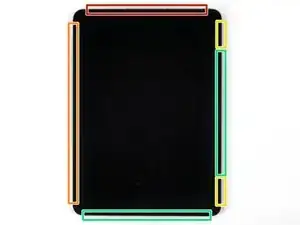
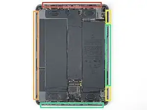
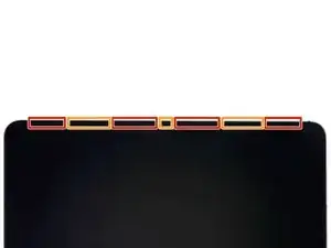
    • While your iPad looks uniform from the outside, there are delicate components under portions of the screen. To avoid damage, follow instructions exactly as written and note the following areas as you open your iPad:

    • Camera module, ambient light sensors, proximity senor, and front microphone

    • Display cables

    • Screen magnets

    • LCD edges

  3. SWfJNvV3tpPHfafG
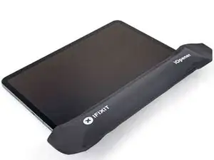
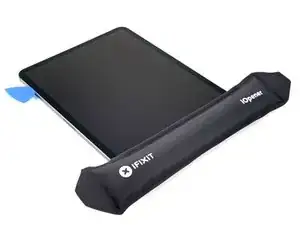
    • Apply a heated iOpener to the right edge of the screen for two minutes.

    • You can also use a hair dryer, heat gun, or hot plate—but extreme heat can damage the screen and/or internal battery, so proceed with care.

    If using a heat gun, what would be the ideal temperature?

    geddy76 -

  4. PPuOSHSXPsGqUfKY
    PPuOSHSXPsGqUfKY
    OfG3iuJl2cZPUEW3
    SJquXDd2yvg4QmZs
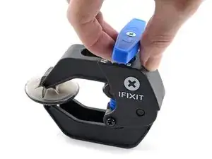
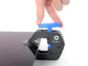
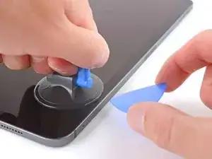
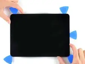
    • The next three steps demonstrate the Anti-Clamp, a tool we designed to make the opening procedure easier. If you aren't using the Anti-Clamp, skip down three steps for an alternate method.

    • For complete instructions on how to use the Anti-Clamp, check out this guide.

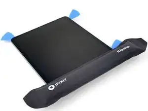
    • Pull the blue handle backward to unlock the Anti-Clamp's arms.

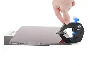
    • Place an object under your iPad so it rests level between the suction cups.

    • Position the suction cups near the middle of the right edge—one on the top, and one on the bottom.

    • Hold the bottom of the Anti-Clamp steady and firmly press down on the top cup to apply suction.

    • If you find that the surface of your iPad is too slippery for the Anti-Clamp to hold onto, use tape to create a grippier surface.

  5. jWtSO54fkgJsFeqY
    jWtSO54fkgJsFeqY
    yFNsRNhMKmpWS5ae
    XbkWbXPnGlcRHYCq
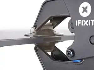
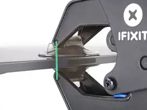
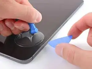
    • Pull the blue handle forward to lock the arms.

    • Turn the handle clockwise 360 degrees or until the cups start to stretch.

    • Make sure the suction cups remain aligned with each other. If they begin to slip out of alignment, loosen the suction cups slightly and realign the arms.

  6. Xbgn3IG4xSflXGeB
    Xbgn3IG4xSflXGeB
    vOVZU2YdZUfXnLfF
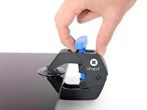
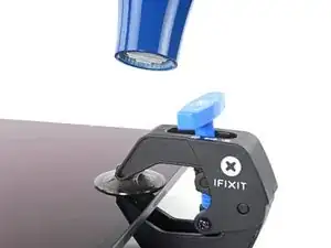
    • Wait one minute to give the adhesive a chance to release and present an opening gap.

    • If your screen isn't getting hot enough, you can use a hair dryer to heat along the right edge of the iPad.

    • For complete instructions on how to use a hair dryer, check out this guide.

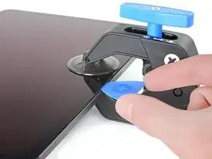
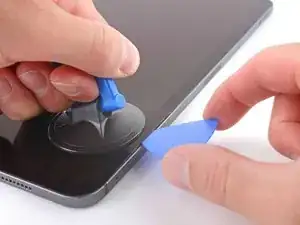
    • Insert an opening pick under the screen when the Anti-Clamp creates a large enough gap.

    • If the Anti-Clamp doesn't create a sufficient gap, apply more heat to the area and rotate the handle clockwise half a turn.

    • Don't crank more than a half a turn at a time, and wait one minute between turns. Let the Anti-Clamp and time do the work for you.

    • Skip the next step.

  7. UudD4HWgdf6lDhBA
    UudD4HWgdf6lDhBA
    tpVS1HUCPF3rsvFs
    y5AHt5ojeGJ5sKMG
    • If your screen is badly cracked, covering it with a layer of clear packing tape may allow the suction cup to adhere. Alternatively, very strong tape may be used instead of the suction cup. If all else fails, you can superglue the suction cup to the broken screen.

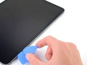
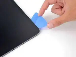
    • Apply a suction handle to the right edge of the screen, about 5 cm from the bottom edge.

    • Pull up on the suction handle with firm, constant pressure to create a gap just small enough to insert an opening pick.

    • Only create a gap small enough to insert an opening pick. Overbending the screen will damage it.

    • Insert the tip of an opening pick into the gap.

    • Don't insert the opening pick more than 5 mm or you may damage the LCD.

  8. gKQcNDfaXmlg5WJr
    gKQcNDfaXmlg5WJr
    MBpw1FqIkISOBgaF
    PMrdneUcwwTAQbZX
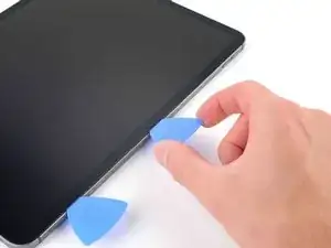
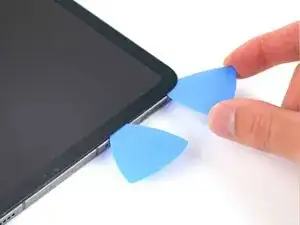
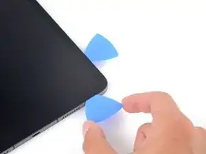
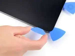
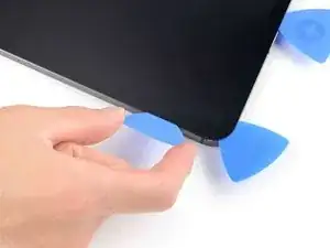
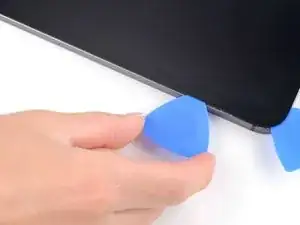
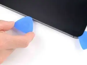
    • Insert a new opening pick in the gap you just created.

    • Slide the pick along the right edge to separate the adhesive.

    • When sliding near the volume buttons, don't insert the pick more than 2 mm or you'll damage the screen magnets.

    • Leave the pick in the top right corner to prevent the adhesive from re-sealing.

  9. aSAPlEm3Caw4yTrM
    • Apply a heated iOpener to the top edge of the screen for two minutes.

  10. GddBVSwJBIwTXfmN
    GddBVSwJBIwTXfmN
    fIOfSXr5cYPgv6th
    Hnb1oiHr2tGBYnHy
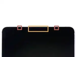
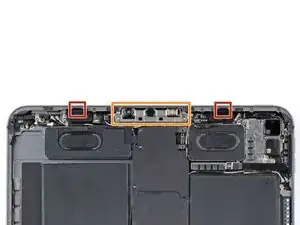
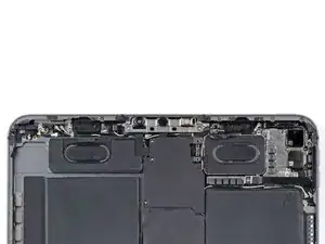
    • The top edge of the iPad contains the camera module, two ambient light sensors, the proximity sensor, and front microphone. These components are fragile and easily damaged if an opening pick is inserted too far. Only separate the adhesive in the marked locations to avoid damage.

    • The two ambient light sensors can be hard to see and can be located using a flashlight or by placing the iPad under a bright light.

    • Don't insert an opening pick more than 2 mm near the top left and right edges or you'll damage the ambient light sensors.

    • Don't insert an opening pick more than 1 mm near the middle of the top edge or you'll damage the camera module, proximity sensor, and front microphone.

  11. X4ERXwlrTnfpPamA
    X4ERXwlrTnfpPamA
    DnQAY3CsT4PdiRdF
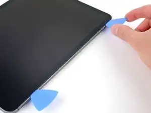
    • Insert a new opening pick in the gap you just created.

    • Slide the pick along the top right edge, stopping when you reach the right ambient light sensor.

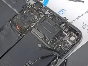
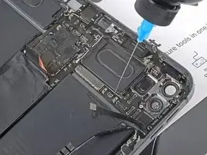
    • Don't insert the opening pick more than 5 mm.

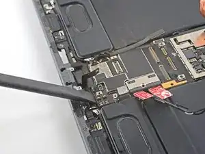
    • Leave the pick in to prevent the adhesive from re-sealing.

  12. MSlUONmmoqsYWGpG
    MSlUONmmoqsYWGpG
    OqDYIwFnaCmVCN6g
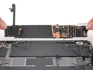
    AswnMuPEcO2JiM5C
    • Insert a new opening pick to the right of the ambient light sensor.

    • Slide the pick along the middle section of the top edge, stopping when you reach the left ambient light sensor.

    • Don't insert the pick more than 1 mm or you'll damage the proximity sensor and front microphone.

    • Leave the pick in to prevent the adhesive from re-sealing.

  13. oPYYrsL54NpdCwFJ
    oPYYrsL54NpdCwFJ
    nZLYAslhDhm1nvCI
    • Insert a new opening pick to the left of the ambient light sensor.

    • Slide the pick along the top left edge, stopping when you reach the left ambient light sensor.

    • Don't insert the opening pick more than 5 mm.

    • Once the top edge adhesive has been separated, you can remove the two picks near the ambient light sensors.

  14. M4QlliPhG13xJHQW
    • Apply a heated iOpener to the bottom edge of the screen for two minutes.

  15. 45WV5NHKBLSSQjmA
    45WV5NHKBLSSQjmA
    kfyWxXwmTIoaycAR
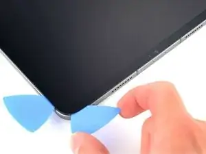
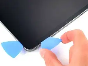
    • Insert a new opening pick in the bottom right corner below the existing pick.

    • Don't insert the opening pick more than 2 mm when sliding on the right edge.

    • Slide the pick around the bottom right corner to separate the adhesive.

  16. ZfcRVWBmGZ2joXtW
    ZfcRVWBmGZ2joXtW
    YpQXhA3yINtV4NLv
    • Slide the opening pick along the bottom edge, stopping at the USB-C port.

    • Don't insert the opening pick more than 5 mm when separating the bottom edge adhesive.

    • Leave the pick in to prevent the bottom edge adhesive from re-sealing.

  17. SCS1DRKPEyojXcQr
    SCS1DRKPEyojXcQr
    RdHjD4ZJxPPoDoZX
    • Insert a new opening pick to the left of the USB-C port.

    • Separate the remaining bottom edge adhesive.

    • Don't insert the opening pick more than 5 mm when slicing the bottom edge adhesive.

    • Leave the pick in the bottom left corner to prevent the bottom edge adhesive from re-sealing.

  18. BBRHcwn6APDESJMU
    • Apply a heated iOpener to the left edge of the screen for two minutes.

  19. F5n3jEJUogHmRBfj
    F5n3jEJUogHmRBfj
    PZBQpBnJTlbofLVC
    QNWw1FUrnA1IveRa
    • The left edge of the iPad contains several display cables. These cables are extremely fragile and easily damaged if an opening pick is inserted too far or at the wrong angle. Follow the instructions exactly as written to avoid damage.

    • The display cables are located within small indents of the frame and require an opening pick to be inserted at a 45° angle.

    • There are flat sections of the frame which require an opening pick to be inserted horizontally.

  20. fFSKShSGUIXXRGEH
    fFSKShSGUIXXRGEH
    oG4S2tOjoD2XxPXA
    • Insert an opening pick at a 45˚ angle just above the bottom left corner.

    • Don't insert the pick more than 5 mm or you'll damage the display cables.

    • Carefully slide the pick along the left edge, stopping when you reach the flat section of the frame.

  21. sB62OFGs4RLtyKwE
    sB62OFGs4RLtyKwE
    bNHEJkP1QbVBx3Le
    • Lower the opening pick so it is horizontal to the screen.

    • Don't insert the pick more than 5 mm.

    • Continue separating the left edge adhesive until you reach the next indented section of the frame.

  22. 6DCbGkbndP6p6PIv
    • Separate the remaining adhesive, making sure to follow the instructions exactly as written.

    • Slide the pick at a 45˚ downward angle and don't insert the pick more than 5 mm.

    • Slide the pick horizontally and don't insert the pick more than 5 mm.

  23. tcFjW3mSfk3T31YN
    tcFjW3mSfk3T31YN
    v1n2MwlpuNvDlIsY
    gCPwdGt3DlxwSKLQ
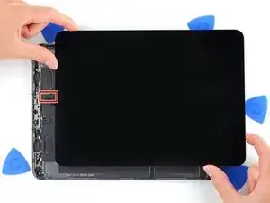
    • At this point, you've separated most of the screen adhesive. Lift the edges of the screen up slightly to check if there is any remaining adhesive.

    • Use an opening pick to remove any remaining adhesive keeping the screen stuck to the frame.

    • Grab the top right and bottom left corners of the screen.

    • Slowly slide the screen towards the bottom right corner to separate it from the frame.

    • Don't fully remove the screen as it is held in place by several ribbon cables underneath.

    • Shift the screen towards the bottom right corner of the frame until the ambient light sensor ribbon cable near the top edge is uncovered.

    This (step 23) is by far the hardest part, the glue, even in warmed-up state, is quite strong and the panel extremely fragile.

    ifaxit -

  24. eV4OvPRVSBIcp1tY
    eV4OvPRVSBIcp1tY
    iVwae1KkhePPfNmY
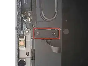
    • Throughout this repair, keep track of each screw and make sure it goes back exactly where it came from.

    • Use a Phillips screwdriver to remove the two screws securing the ambient light sensor cable bracket to the logic board:

    • One 1.3 mm screw

    • One 2.0 mm screw

    • During reassembly, this is a good point to power on your iPad and test all functions before sealing it up. Be sure to power your iPad back down before you continue working.

  25. wg1fGoMjlmJVL5aI
    • Use a pair of tweezers or your fingers to remove the bracket.

  26. 6ZrxyCxJShZWSVbx
    6ZrxyCxJShZWSVbx
    DnnoCmSipQ5uYkJI
    • Use the flat end of a spudger to disconnect the ambient light sensor cable by lifting straight up on the press connectors.

    • To re-attach press connectors like this one, carefully align and press down on one side until it clicks into place, then repeat on the other side. Do not press down on the middle. If the connector is misaligned, the pins can bend and cause permanent damage.

  27. NejYRMNOxSFxrBuR
    NejYRMNOxSFxrBuR
    5PWXb6IRNv6GQxvu
    jutHpQmBENyNKJAA
    • Don't try to remove the screen yet, as it's still attached by delicate ribbon cables.

    • Grip the right edge of the screen and fold it open like a book.

    • Lay the screen down over the left edge of the iPad.

  28. KrdjGIhaDutm4BLD
    KrdjGIhaDutm4BLD
    rqRXkXVFYNGuMqfN
    • Use a Phillips screwdriver to remove the five screws securing the lower cable shield to the logic board:

    • Two 2.0 mm screws

    • Three 1.3 mm screws

  29. ayiAkOBcA4M3MQZO
    • Use tweezers or your fingers to grab and remove the lower cable shield.

  30. UwfpTYKfOAnwqQAB
    UwfpTYKfOAnwqQAB
    huDrXWDACcMgCPul
    • Use a Phillips screwdriver to remove the 1.8 mm screw securing the battery connector to the logic board.

    insert plastic sliver to disconnect the battery. Most important step not written down!

    Jack -

  31. hb4aWKRHCDmmSRVB
    hb4aWKRHCDmmSRVB
    B3Xy2Vxj4eK5lSVE
    cVNQAyeKgZnZyBTC
    • Use the pointed end of a spudger to pry up and disconnect the top two display cables.

  32. ZbHWsCPOofIWHcNt
    ZbHWsCPOofIWHcNt
    tJApCQr5ufqJPfiP
    bsoH3fv41niYEysg
    • Disconnect the two remaining display cables.

  33. dnQviK5MA3rPPWbO
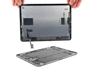
    • Grip the right edge of the screen and lift it away.

    • During reassembly, before installing a screen, remove any remaining adhesive from the frame, and clean the glued areas with high-strength (>90%) isopropyl alcohol and a lint-free cloth. This helps prep the iPad for fresh adhesive and ensures that it will bond properly.

    • If you plan to reinstall your existing screen, remove any remaining adhesive from the back and clean the adhered areas with isopropyl alcohol.

    • Follow this guide to install pre-cut adhesive strips on your iPad before sealing it up.

  34. XxJO1IWQTAaVWARB
    XxJO1IWQTAaVWARB
    UkpqywGGCgkCO1kM
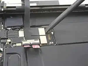
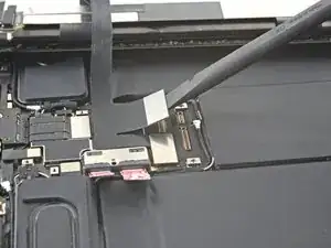
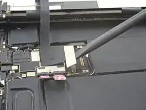
    • Use the flat end of a spudger to disconnect the USB-C port cable.

  35. MEHFXQctM3R1MU2i
    MEHFXQctM3R1MU2i
    R1jwmaT4Ns1UZvaM
    i5ianyZEK13DXNaC
    • The USB-C port cable is secured to the logic board with weak adhesive.

    • Slide an opening pick between the cable and the logic board to separate the adhesive.

  36. tEtkwEPVuehbujSW
    tEtkwEPVuehbujSW
    cb4h3lF1GRsLIpPV
    • Use a Phillips screwdriver to remove the two 1.9 mm screws securing the USB-C port to the frame.

  37. NFA3CVbvcDdpKsdl
    NFA3CVbvcDdpKsdl
    sNrwIbcLwGOkG3Tj
    YIBiMZpDcyjeRrxX
    • Use tweezers to remove the two grounding contacts from each side of the USB-C port.

  38. uZCSlUOyVdLqKD3r
    uZCSlUOyVdLqKD3r
    x1IfRIHYc1EJKvS4
    • Lift up and remove the USB-C port.

  39. 3aNRQaFN3Fo1TtLl
    3aNRQaFN3Fo1TtLl
    KNFYASGBVPOjYptx
    • Use a Phillips screwdriver to remove the three 1.2 mm screws securing the top cable shield.

  40. gVG2Aro3GDLLQjWy
    gVG2Aro3GDLLQjWy
    FVGBlDmdXoSBtpvN
    • Apply a heated iOpener to the top cable shield for one minute to soften the adhesive securing it to the logic board.

  41. Wq4mxgRZVQfULSNR
    Wq4mxgRZVQfULSNR
    YVaShXAEfRQSHrIB
    5JLgQJsgtNtdeMP4
    • Insert an opening pick under the top cable shield and gently pry up to separate the adhesive.

  42. rcdDpkGhyBTNDw2B
    rcdDpkGhyBTNDw2B
    Gr2TqabCdcChaPog
    • Use tweezers or your fingers to grab and remove the top cable shield.

  43. OutE3qkeehcofLUc
    OutE3qkeehcofLUc
    NRBdrUbGkiVAfsJW
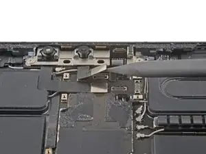
    • Use the pointed end of a spudger to disconnect the IR dot projector cable.

  44. GqbHZTSlrBG1MB3I
    GqbHZTSlrBG1MB3I
    v4ymEYMKdG5afSdF
    6LR5LSRkv5o11iEi
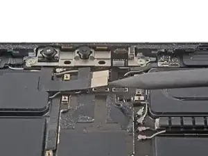
    • Use the pointed end of a spudger to disconnect the front-facing camera and Face ID camera.

  45. bFJFJDnvrmNSMe6O
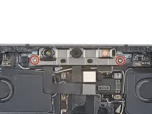
    • Use a Torx T3 screwdriver to remove the two 2.1 mm screws securing the front camera assembly to the frame.

  46. GdfVCjSlJdveEPpL
    GdfVCjSlJdveEPpL
    k12QfEMPSBuDPdPZ
    JA2QWeiV2pQ2NX5L
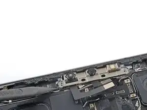
    • Use the pointed end of a spudger to pry up and loosen the front camera assembly.

    • Use tweezers or your fingers to remove the front camera assembly.

  47. LUckwdTNPkZ6Zo1h
    LUckwdTNPkZ6Zo1h
    ZcrZ3aA6aQs4wIQH
    N5nXwLPML1VJKvdB
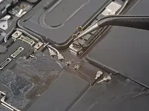
    • To disconnect antenna cables like this, use tweezers to grip the connector near the cable and lift it up.

    • Use tweezers to disconnect the two antenna cables.

    • Be careful using tweezers or other pointy metal tools near the battery—a punctured battery may leak dangerous chemicals or cause a fire.

    • To reinstall, hold the connector in place and gently press straight down. The connector will “snap” into its socket much like the metal snaps on a jacket.

  48. L5DhfnplJvYXG3ab
    L5DhfnplJvYXG3ab
    b4CGufYYEoVIYh2h
    uHAbIo6WCLhCX6eg
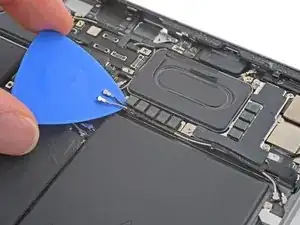
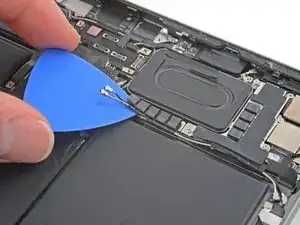
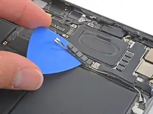
    • The antenna cables are secured to the logic board with weak adhesive.

    • Slide an opening pick under the antenna cables to separate them from the logic board.

  49. RUhCQcb2nINHM1nh
    RUhCQcb2nINHM1nh
    YwrpUEiWDALPprcW
    wZQcsRfYX2gtyfwU
    • Use an opening pick to separate the thin foam covering the antenna cables.

  50. f55pAJEAKqZyoOY1
    f55pAJEAKqZyoOY1
    2OiwUXFW3MUG1tSF
    absv6uUY2EkdalF2
    • The antenna cables are secured to the mmWave interconnect cable with weak adhesive.

    • Slide an opening pick between the antenna cables and the mmWave interconnect cable to separate them.

  51. V2wObDXYpVJosOGG
    V2wObDXYpVJosOGG
    HqOFA6IDPLkYQyXk
    • Use a Phillips screwdriver to remove the 1.2 mm screw securing the press connector bracket to the logic board.

  52. SOmIGAnMtAbs3dcl
    SOmIGAnMtAbs3dcl
    jJBLt14s3ZoWNsFv
    • Use tweezers or your fingers to remove the antenna cable bracket.

    • Be careful using tweezers or other pointy metal tools near the battery—a punctured battery may leak dangerous chemicals or cause a fire.

  53. EnyFpIfZLYAL66gl
    EnyFpIfZLYAL66gl
    VUIXFgHvUpjaZiDh
    • Use the flat end of a spudger to disconnect the mmWave flex cable.

  54. S2IfyNELWrXiSuIt
    S2IfyNELWrXiSuIt
    Cte2b1OS2jrgFlDT
    3gZZSxi5XNuYTqJn
    • Slide an opening pick under the mmWave flex cable to separate it from the logic board.

  55. HOcEGVLWuCVNvAaY
    HOcEGVLWuCVNvAaY
    mXraVtA2yR4wRSxw
    • Some of these screws are the same length but have different thread sizes. Don't mix up the screws or you'll damage the threads in the frame.

    • Use your Phillips screwdriver to remove the six screws securing the rear camera shield to the frame:

    • Two 2.8 mm screws

    • One 1.9 mm screw

    • One 1.9 mm screw

    • One 1.2 mm screw

    • One 1.2 mm screw

  56. E1KnWospAoNKLctL
    E1KnWospAoNKLctL
    IUVdHojiSAASE5t1
    FZAUyIfPmYTGo5wF
    • Use tweezers or your fingers to lift the right side of the camera shield up.

    • Slide the shield out horizontally.

    • During reassembly, lower the left side of the shield back into place and make sure the small protruding tab is slotted in, then hinge the shield closed.

  57. jDVKpkQ4NWDZZyJd
    jDVKpkQ4NWDZZyJd
    UmSXBjCsKiheytuX
    • Use the pointed end of a spudger to disconnect the wide angle camera cable.

  58. HUrDQnRdPGC3RSr2
    HUrDQnRdPGC3RSr2
    FQmW1RCqVGkqQG5N
    MatU2PKfFBEDfwNE
    • Use the pointed end of a spudger to disconnect the power button and LED cable.

  59. snXnCkvSCmJ6pLDI
    snXnCkvSCmJ6pLDI
    qaSgiqeZZrjlgwZM
    RixQbGIKZLofGyux
    • Use the flat end of a spudger to disconnect the LiDAR sensor cable.

    • Fold the LiDAR sensor cable away from the frame to access the press connectors underneath.

    • Only fold the cable enough to access the connector underneath.

  60. WPIVn3OZUF2Jqo2t
    WPIVn3OZUF2Jqo2t
    obMkPWYlEwthdBGk
    • Use the pointed edge of a spudger to disconnect the ultra wide camera cable.

  61. Wk2MHmTTgY1jFsQy
    Wk2MHmTTgY1jFsQy
    p5VTtTdBGvond2tU
    oiUc6ZIilFEqWDEi
    • Use the flat end of a spudger to gently pry up and loosen the rear camera module.

    • Use tweezers or your fingers to grab and remove the rear camera module.

  62. nvjnqtnauiOX6TlY
    nvjnqtnauiOX6TlY
    mgtXAbrdX3wDDpDr
    • You're about to disconnect many connectors from the top and bottom of the logic board. During reassembly, use these photos as a reference to ensure all cables are connected in the correct locations.

  63. KuFX1lMEdpd2MYoF
    KuFX1lMEdpd2MYoF
    6UDNku2a23euYmTX
    NNrgX2Dtt5LaJVKX
    • Use the pointed end of a spudger to disconnect the two top right speaker press connectors.

    • Don't pry against the short sides of the connector. The socket on the logic board is delicate and may break off if pried against.

  64. DguE3MIwBUrbAFiK
    DguE3MIwBUrbAFiK
    PI3rAu1H3iF3loaa
    YpORYAmROvEBRloO
    • Repeat the previous step for the two top left speaker cables.

  65. IHOAqLV1vR4erOsy
    IHOAqLV1vR4erOsy
    YrLHfmB1WsAapIU5
    • Use the pointed edge of a spudger to disconnect the top microphone cable.

  66. SHU6jbeY2sYThi12
    SHU6jbeY2sYThi12
    FCKdCSemQy2Wje12
    • Use the pointed end of a spudger to disconnect the top right sensor cable.

  67. lKZLVrMPmHK5naDs
    lKZLVrMPmHK5naDs
    KP6Sr6SVyPoJd4NN
    • Use the pointed edge of a spudger to disconnect the top interconnect board.

    • Don't bend or reposition the interconnect board. It's stiff and will break if overbent.

  68. seyOApswIKhksmqe
    seyOApswIKhksmqe
    aTgDUNCTsReBq2Wc
    bQASASTumJeIObNd
  69. 1iTkIwTSJyjqQS3g
    1iTkIwTSJyjqQS3g
    TU5LWAQQdIi3wICo
    5aieynY2eY1XVf3o
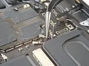
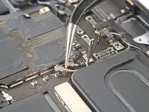
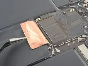
    • Use tweezers to peel back the logic board shielding tape covering the two antenna cables.

    • Be careful using tweezers or other pointy metal tools near the battery—a punctured battery may leak dangerous chemicals or cause a fire.

  70. ILMJfJQfAlVcQqnP
    ILMJfJQfAlVcQqnP
    iUnIDXOQpKYPCDPZ
    rmIXdYi1VvGu2iTS
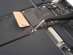
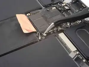
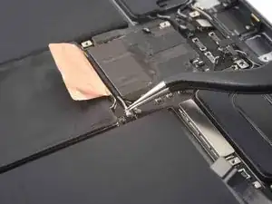
    • Use tweezers to disconnect the two bottom right antenna cables.

    • Be careful using tweezers or other pointy metal tools near the battery—a punctured battery may leak dangerous chemicals or cause a fire.

  71. mXYUxZqHP2BrMUcK
    mXYUxZqHP2BrMUcK
    W3MZvaNimYMasmth
    • Use the pointed edge of a spudger to disconnect the bottom interconnect board.

    • Don't bend or reposition the interconnect board. It's stiff and will break if overbent.

  72. KwWdiVZy3KC3XZv3
    KwWdiVZy3KC3XZv3
    pauAoG32ZPMfJoAR
    • Use tweezers to disconnect the Wi-Fi antenna coaxial cable.

  73. uGiSOUoOAopdPQlv
    uGiSOUoOAopdPQlv
    hFojoybjKLwIdRsC
    • Use the pointed end of a spudger to disconnect the Smart Connector cable.

  74. A1kXdPciT3u6iNat
    A1kXdPciT3u6iNat
    pt6yrNLDZkDrA2kb
    xEUXnUcIav5TkQTp
    • Follow the procedure in step 65 to disconnect the bottom right speaker.

  75. B3G3WxFPHakciEnj
    B3G3WxFPHakciEnj
    4BkmQEqpLliWphGH
    Fl5mZ3RMNZ4Fjmfu
    • Follow the procedure in step 65 to disconnect the bottom right speaker.

  76. CyDUA4aMJrtTNQda
    CyDUA4aMJrtTNQda
    WOy1ClLyE4FkjKxw
    LRJKhXj26xomOSgU
    • Gently pull the antenna cables away from the logic board.

  77. CvtYNpDI6kF126QW
    CvtYNpDI6kF126QW
    DGHBwdV5bHfBlqdU
    xhLgVhpyE4OCwndx
    • Continue repositioning the antenna cables until they are clear from the bottom of the logic board.

  78. eAOMIcLKHPPJLQ3D
    eAOMIcLKHPPJLQ3D
    QsxcCHor5wWKhXIX
    VNAJBKvS3DnXFVXR
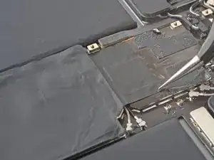
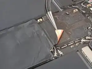
    • Use tweezers or your fingers to peel back the logic board shielding to reveal the hidden press connectors.

    • Be careful using tweezers or other pointy metal tools near the battery—a punctured battery may leak dangerous chemicals or cause a fire.

  79. LmRcNghDW25Shbgx
    LmRcNghDW25Shbgx
    2ARs1LiYF6uDZ63r
    MCyTBCKO5XfJh6ej
    • Use the flat end of a spudger to slide out the cable bracket.

    • Use tweezers or your fingers to remove the bracket.

  80. dGdhF3BxRphGTHTA
    dGdhF3BxRphGTHTA
    FfW3KN1eq2qrTIIR
    xxtyDnBT6wC2ojS4
    • Use the flat end of a spudger to disconnect the left microphone and Apple Pencil charger cables.

  81. U2PelVjNgkbHnVRq
    U2PelVjNgkbHnVRq
    OdAgjGHDpOl1eKWB
    K6noOQXUsIeG33je
    • The adhesive that secures the logic board to the frame is very strong. To remove the board, follow the next steps to weaken the adhesive using high-strength (>90%) isopropyl alcohol.

    • Elevate the left side of the iPad so that it lays down at an angle.

    • Apply a few drops of isopropyl alcohol along the left edge of the logic board.

    • Be careful if you're using a syringe with a needle or other sharp instrument to dispense isopropyl alcohol—a punctured or bent battery may leak dangerous chemicals or cause a fire.

    • Let the alcohol soak for one minute to soften the adhesive under the logic board.

  82. jJDx5XwTyadHZRPq
    jJDx5XwTyadHZRPq
    B5VcCOp32iaECCPq
    EaWJYEHPklgmKMYZ
    • Rotate your iPad 180˚ and lay it down with the right side elevated.

    • Repeat the previous step for the right edge of the logic board.

  83. jC2dZJ5sDuaTBLew
    jC2dZJ5sDuaTBLew
    VBiLfRVOfsJ1FGXX
    • Elevate the top side of the iPad.

    • Apply a few drops of isopropyl alcohol to the right branch of the logic board near the rear camera glass.

    • Don't allow isopropyl alcohol to contact the rear camera glass or you'll damage them.

    • Let the alcohol soak for one minute to soften the adhesive under the right logic board branch.

  84. l5yYFFxZhEPKUv2s
    l5yYFFxZhEPKUv2s
    SZwxsZbmrfo24Pdn
    4G4vlQ1QINw1tbQP
    • Insert the flat end of a spudger under the lower edge of the logic board.

    • Don't pry against the bottom interconnect board as this will damage it.

    • Slowly lift up the bottom of the logic board.

    • If the adhesive is still too strong to lift up the logic board, apply some additional isopropyl alcohol and wait one minute.

    • Lift up the logic board and replace the playing card battery blocker with an opening pick.

  85. kOHJffHyxxf3auib
    kOHJffHyxxf3auib
    BtKdR5iEeHe3nhbu
    kyBQ6S2rWQrwBCBS
    • Slide an opening pick under the left edge of the logic board to loosen it.

    • Pry against the frame underneath the logic board to separate the adhesive.

    • Don't forcefully lever against the battery—a punctured or bent battery may leak dangerous chemicals or cause a fire.

    • If the adhesive is still too strong to lift up the logic board, apply some additional isopropyl alcohol and wait one minute.

  86. WFUkJ52fO6WV3kmy
    WFUkJ52fO6WV3kmy
    LSRSHmtXECFHUtB3
    fvxGtmhxsbJu5wfC
    • Use an opening pick to gently pry up the top right branch of the logic board near the rear camera lenses.

    • If the adhesive is still too strong to lift up the logic board, apply some additional isopropyl alcohol and wait one minute.

  87. ZtH3fQQR2NgIZiVQ
    ZtH3fQQR2NgIZiVQ
    iEG6qgP3aHDrxnPr
    • Insert an opening pick under the right edge of the logic board above the left microphone and Apple Pencil charger cables.

    • Slide the opening pick under the right edge of the logic board to loosen it.

    • Pry against the frame underneath the logic board to separate the adhesive.

    • Don't forcefully lever against the battery—a punctured or bent battery may leak dangerous chemicals or cause a fire.

    • If the adhesive is still too strong to lift up the logic board, apply some additional isopropyl alcohol and wait one minute.

  88. rROTrnwhv2VFZPlC
    rROTrnwhv2VFZPlC
    QXRTcCISnnT5lCI3
    RKfFjdgTs6uXalPC
    • Use the flat end of a spudger to lift the top edge of the logic board.

    • Grip the top and bottom edges of the logic board.

    • Remove the logic board.

Conclusion

Compare your new replacement part to the original part—you may need to transfer remaining components or remove adhesive backings from the new part before installing.

To reassemble your device, follow these instructions in reverse order.

Take your e-waste to an R2 or e-Stewards certified recycler.

Repair didn’t go as planned? Try some basic troubleshooting, or ask our iPad Pro 11" 3rd Gen Answers community for help.
Chayton Ritter

Member since: 21/08/20

20864 Reputation

0 comments