.jpg.webp)
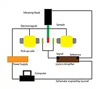
A vibrating-sample magnetometer (VSM) (also referred to as a Foner magnetometer) is a scientific instrument that measures magnetic properties based on Faraday’s Law of Induction. Simon Foner at MIT Lincoln Laboratory invented VSM in 1955 and reported it in 1959.[1] Also it was mentioned by G.W. Van Oosterhout[2] and by P.J Flanders in 1956.[3] A sample is first placed in a constant magnetic field and if the sample is magnetic it will align its magnetization with the external field. The magnetic dipole moment of the sample creates a magnetic field that changes as a function of time as the sample is moved up and down. This is typically done through the use of a piezoelectric material. The alternating magnetic field induces an electric field in the pickup coils of the VSM.[4] The current is proportional to the magnetization of the sample - the greater the induced current, the greater the magnetization. As a result, typically a hysteresis curve will be recorded[5] and from there the magnetic properties of the sample can be deduced.
The idea of vibrating sample came from D. O. Smith's[6] vibrating-coil magnetometer.
Typical VSM overview
Parts of a typical VSM setup

- Actively cooled electromagnet/power supply
- Amplifier
- Control Chassis
- Meter
- Computer interface
- Sensor coils
- Vibration exciter with sample holder
- Hall probe (optional)
Sample Operating Procedure:[4]
Conditions for VSM to be effective
- Magnetic field must be strong enough to fully saturate the samples (or else inaccurate measurements will be taken)
- Magnetic field must be uniform across the sample space (otherwise the addition of field gradients[5][7] will induce force that alter the vibration once again leading to inaccurate results
Importance of pick-up coils
These allow the VSM to maximize the induced signal, reduce the noise, give a wide saddle point, minimize the volume in between the sample and electromagnet to achieve a more uniform magnetic field at the sample space.[5] The configuration of the coils can vary depending on the type of material being studied.[5]
Relation to Physics
The VSM relies on Faraday's law of induction, with the detection of the emf given by ,[7] where N is the number of wire turns, A is the area, and the angle between the normal of the coil and the B field. However, N and A are often unnecessary if the VSM is properly calibrated.[7] By varying the strength of the electromagnet through computer software, the external field is sweeped from high to low and back to high.[7] Typically this is automated through a computer process and a cycle of data is printed out. The electromagnet is typically attached to a rotating base[7] so as to allow the measurements be taken as a function of angle. The external field is applied parallel to the sample length[7] and the aforementioned cycle prints out a hysteresis loop. Then using known magnetization of the calibration material and wire volume the high field voltage signal can be converted into emu units - useful for analysis.[7]
Advantages and Disadvantages
The precision and accuracy of VSM's are quite high even among other magnetometers and can be on the order of ~ emu.[5] VSM's further allow for a sample to be tested at varying angles with respect to its magnetization letting researchers minimize the effects of external influences.[8] However, VSM's are not well suited for determining the magnetization loop due to the demagnetizing effects incurred by the sample.[8] VSM's further suffer from temperature dependence and cannot be used on fragile samples that cannot undergo acceleration (from the vibration).[5][7][8]
References
- ↑ Foner, Simon (1959). "Versatile and Sensitive Vibrating-Sample Magnetometer". Rev. Sci. Instrum. 30 (7): 548–557. Bibcode:1959RScI...30..548F. doi:10.1063/1.1716679.
- ↑ Van Oosterhout, G.W. (1956). Appl. Sci. Res. B6: 101.
{{cite journal}}: Missing or empty|title=(help) - ↑ Flanders, P.J. (1956). IEEE Special Publication, Conference on Magnetism and Magnetic Materials. T-91: 315–317.
{{cite journal}}: Missing or empty|title=(help) - 1 2 3 SWT Physics Department. "Vibrating Sample Magnetometer" (PDF).
- 1 2 3 4 5 6 Lopez-Dominguez, V.; Quesada, A.; Guzmán-Mínguez, J. C.; Moreno, L.; Lere, M.; Spottorno, J.; Giacomone, F.; Fernández, J. F.; Hernando, A.; García, M. A. (2018-03-01). "A simple vibrating sample magnetometer for macroscopic samples". Review of Scientific Instruments. 89 (3): 034707. Bibcode:2018RScI...89c4707L. doi:10.1063/1.5017708. hdl:10261/163494. ISSN 0034-6748. PMID 29604780.
- ↑ Smith, D. O. (1956). "Development of a Vibrating‐Coil Magnetometer". Rev. Sci. Instrum. 27 (261): 261–268. Bibcode:1956RScI...27..261S. doi:10.1063/1.1715538.
- 1 2 3 4 5 6 7 8 Burgei, Wesley; Pechan, Michael J.; Jaeger, Herbert (2003-07-10). "A simple vibrating sample magnetometer for use in a materials physics course". American Journal of Physics. 71 (8): 825–828. Bibcode:2003AmJPh..71..825B. doi:10.1119/1.1572149. ISSN 0002-9505.
- 1 2 3 "Interpretation of Vibrating Sample Magnetometer (VSM) analysis". analyzetest.com. 2021-03-16. Retrieved 2021-05-14.
See also
- Magnetometer
- Alternating (Field) Gradient Magnetometer (AFGM or AGM)
- SQUID Magnetometer