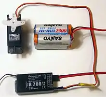

Servo control is a method of controlling many types of RC/hobbyist servos by sending the servo a PWM (pulse-width modulation) signal, a series of repeating pulses of variable width where either the width of the pulse (most common modern hobby servos) or the duty cycle of a pulse train (less common today) determines the position to be achieved by the servo. The PWM signal might come from a radio control receiver to the servo or from common microcontrollers such as the Arduino.
Small hobby servos (often called radio control, or RC servos) are connected through a standard three-wire connection: two wires for a DC power supply and one for control, carrying the control pulses.
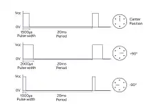
The parameters for the pulses are the minimal pulse width, the maximal pulse width, and the repetition rate. Given the rotation constraints of the servo, neutral is defined to be the center of rotation. Different servos will have different constraints on their rotation, but the neutral position is always around 1.5 milliseconds (ms) pulse width.
Pulse duration
In modern RC servos the angle of mechanical rotation is determined by the width of an electrical pulse that is applied to the control wire. This is a form of pulse-width modulation. The typical RC servo expects to see a pulse every 20 ms, however this can vary within a wide range that differs from servo to servo. The width of the pulse will determine how far the motor turns. For example, in many RC servos a 1.5 ms pulse will make the motor turn to the 90° position (neutral position). The low time (and the total period) can vary over a wide range, and vary from one pulse to the next, without any effect on the position of the servo motor.
Modern RC servo position is not defined by the PWM duty cycle (i.e., ON vs. OFF time) but only by the width of the pulse. (This is different from the PWM used, for example, in some DC motor speed control). Most RC servos move to the same position when they receive a 1.5 ms pulse every 6 ms (a duty cycle of 25%) as when they receive a 1.5 ms pulse every 25 ms (a duty cycle of 6%) – in both cases, they turn to the central position (neutral position). With many RC servos, as long as the refresh rate (how many times per second the pulse is sent, a.k.a. the pulse repetition rate) is in a range of 40 Hz to 200 Hz, the exact value of the refresh rate is irrelevant.[1][2][3][4][5][6][7][8][9]
The period of 20 ms (50 Hz) comes from the days where the signal was encoded in PPM (pulse-position modulation) format to be sent over the air.[10] The PPM period was around 22.5 ms, and the conversion to PWM was trivial: the time of the PWM high state was the time position of the PPM pulse for that servo.
Most RC receivers send pulses to the RC servo at some constant frame rate, changing only the high time. However, it is possible to command an RC servo to move over its entire range with a function generator set to a constant 10% duty cycle by changing only the frequency (frame rate).[11]
Force
When these servos are commanded to move, they will move to the position and hold that position. If an external force pushes against the servo while the servo is holding a position, the servo will resist from moving out of that position. The maximal amount of force the servo can exert is the torque rating of the servo. Servos will only hold their position for their timeout duration, though; the position pulse must be repeated, usually within 20ms, to instruct the servo to stay in position.
Variations
When a pulse is sent to a servo that is less than 1.5 ms, the servo rotates to a position and holds its output shaft some number of degrees counterclockwise from the neutral point. When the pulse is wider than 1.5 ms the opposite occurs. The minimal and maximal widths of pulse that will command the servo to turn to a valid position are functions of each servo. Different brands, and even different servos of the same brand, will have different maxima and minima. Generally, the minimal pulse will be about 1 ms wide, and the maximal pulse will be 2 ms wide.
See also
References
- ↑ Ron Lund. "Servo Frequency and Center Pulse Width Information" Archived 2013-01-19 at the Wayback Machine.
- ↑ Bob Blick. "Servo pulse to PWM converter" "The rate at which pulses are sent to the servo is relatively unimportant".
- ↑ Society of Robots: Servos.
- ↑ Pololu. "Servo control interface in detail" "servo control signals... the frequency of the pulse train does not affect the servo position if the pulse width stays the same".
- ↑ ""Introduction to Servomotor Programming"" (PDF). Archived from the original (PDF) on 2017-08-19. Retrieved 2012-10-23.
- ↑ "Understanding PWM".
- ↑ "servos".
- ↑ 4QD-TEC. "Pulse Width Position Servo".
- ↑ "Servo Control".
- ↑ serge.laforest.free.fr.
- ↑ "Driving the Servo Motor".