Introduction
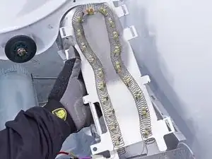
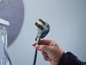
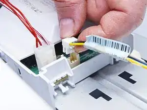
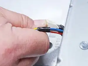
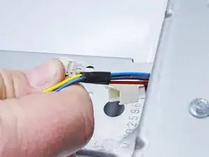
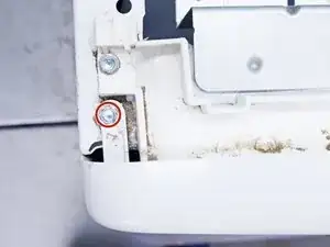
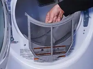
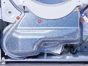
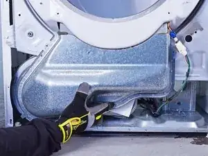
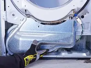
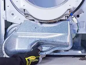
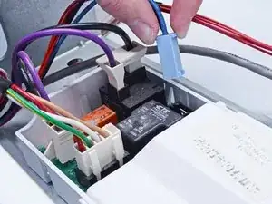
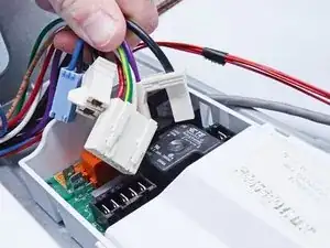
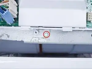
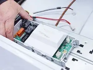
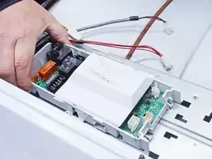
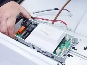
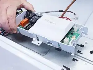
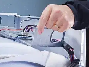
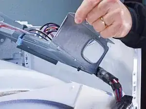
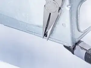
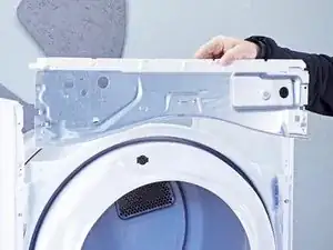
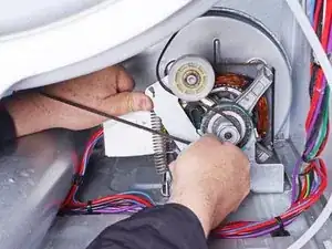
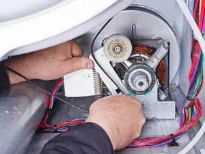
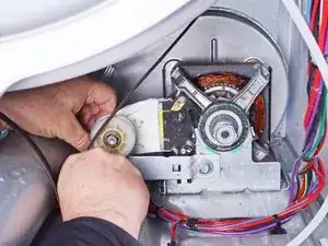
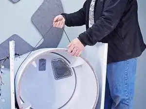
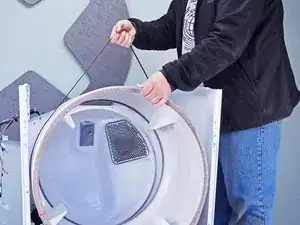
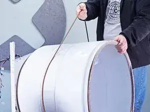
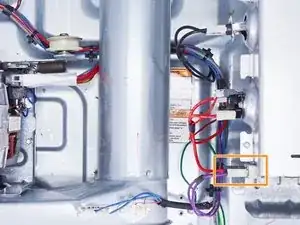
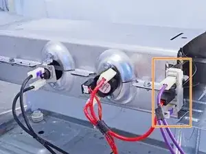
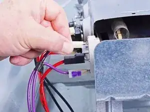
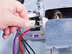
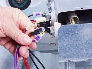
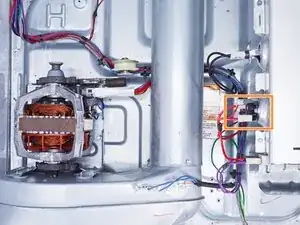
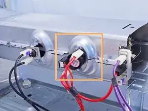
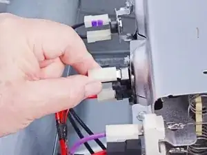
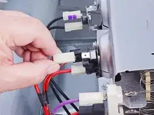
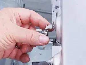
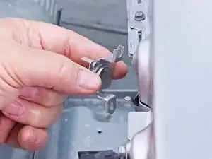
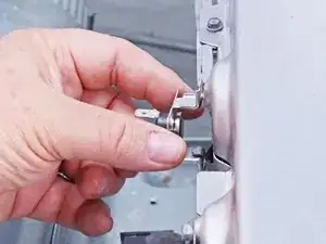
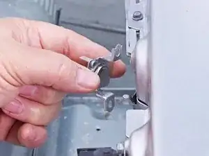
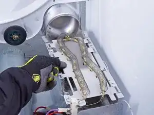
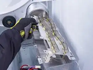
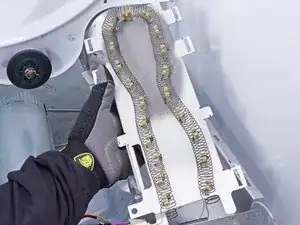
Use this guide if you need to test the heating element in your Whirlpool Duet WED87HED Dryer, and replace it if necessary.
A faulty heating element can cause the dryer to overheat, heat poorly, or not heat at all.
This guide is rated Difficult, and while most of the steps are straightforward, the disassembly and reassembly of the heating element can be tricky in addition to the lower front bulkhead and the drum.
Tools
Parts
-
-
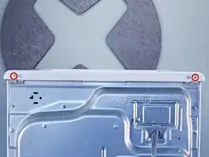
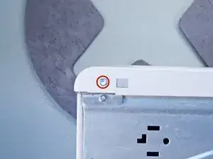
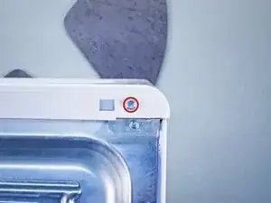
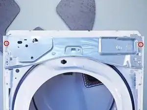
Use a 5/16 inch nut driver to remove the two 15.7 mm-long screws securing the top panel to the rear panel bracket.
-
-
-
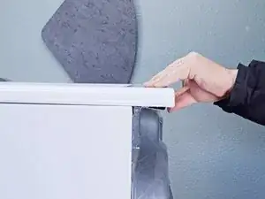
Lift the top panel upward to separate it from the chassis.
-
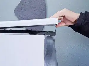
Remove the top panel from the machine.
-
-
-
Use a 1/4 inch nut driver to remove the two 16.3 mm‑long sheet metal screws located at each end of the control panel.
-
-
-
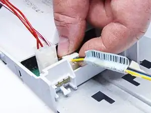
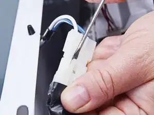
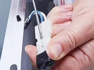
Use a small flat blade screwdriver or a spudger to unlatch both sides of the door switch connector.
-
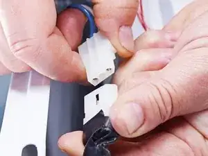
Unplug the connector.
-
-
-
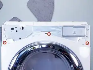
Use a 1/4 inch nut driver to remove the three upper front panel 16.4 mm-long sheet metal screws.
-
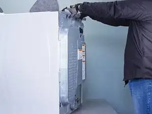
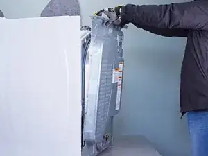
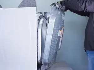
Tilt the machine backwards and prop it securely, or have a friend hold it.
-
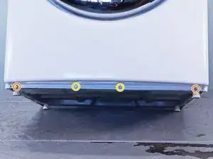
Use a 1/4 inch nut driver to remove the four sheet metal screws on the bottom edge of the panel:
-
Two 16.4 mm screws
-
Two 13 mm screws
-
-
-
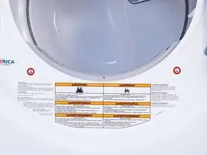
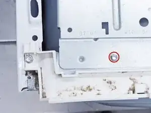
Use a Phillips driver to remove the two 15.8 mm‑long screws inside the door area below the drum opening.
-
-
-
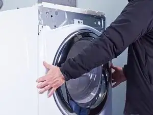
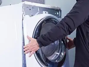
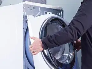
Pull the bottom of the panel away from the chassis about two to three inches.
-
Lift the front panel off the small tabs on the chassis near the top of the panel and remove it.
-
-
-
Use a 5/16 inch hex driver to remove the 16.5 mm-long green ground screw.
-
Use a Phillips driver to remove the two 15.3 mm‑long cord terminal block screws.
-
-
-
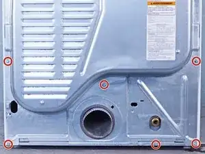
Use a 1/4 inch nut driver to remove the eleven rear panel screws.
-
Ten 20 mm-long screws
-
One 12.9 mm-long screw under the water inlet.
-
-
-
Use a 1/4 inch nut driver to remove the 16.4 mm-length screw holding the main board bracket to the chassis.
-
Use a 1/4 inch nut driver to remove the two 20 mm-long screws from the top rear of the machine.
-
-
-
Lift the panel about 1/2 inch and tilt it to the rear to release it from the vent pipe.
-
Slide the panel off the vent pipe and remove it.
-
-
-
Make sure that the vent pipe is fitted into the collar on the panel.
-
Make sure the tabs at the bottom are aligned to the bottom rim of the chassis.
-
Position the panel so its screw holes match with the chassis.
-
-
-
Use a 1/4 inch nut driver to remove the 16.4 mm‑long mounting screws securing the lint filter housing.
-
-
-
Use a 1/4 inch nut driver to remove the 12.8 mm‑long sheet metal screw that retains the main board to the main board bracket.
-
-
-
Lift the rear corner of the main board nearest to the side walls of the chassis.
-
Slide the main board toward the front of the dryer to release the tabs securing it to the main board bracket.
-
-
-
Use a 1/4 inch nut driver to unfasten the 16.4 mm‑long sheet metal screw holding the main board bracket.
-
-
-
Lift off the main board bracket from the chassis and turn it so the bottom is exposed.
-
Using long nose or slip joint pliers, pinch the locking wings of the harness retainer clamp.
-
Separate the harness from the main board bracket and remove the main board bracket.
-
-
-
Use a 1/4 inch nut driver to remove the two screws securing the upper front bulkhead to the front of the chassis.
-
One 16.4 mm-long sheet metal screw
-
One 19.8 mm-long sheet metal screw
-
Use a 1/4 inch nut driver to remove the two 16.5 mm‑long sheet metal screws securing the top plastic portion to the upper front bulkhead.
-
-
-
Push the idler arm (the metal upside-down "L") up to relieve the tension on the drive belt.
-
Remove the belt from the motor pulley.
-
Gently lower the idler arm until it rests parallel to the dryer floor.
-
-
-
Use a 1/4 inch nut driver to remove the four screws securing the lower front bulkhead.
-
Two 16.1 mm-long sheet metal screws on the left side of the lower front bulkhead.
-
Two 13.2 mm-long sheet metal screws on the right side of the lower front bulkhead.
-
-
-
Lower the bulkhead about 2 inches to free the drum rollers tucked under the drum.
-
While supporting the drum, remove the lower front bulkhead.
-
-
-
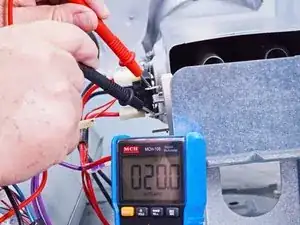
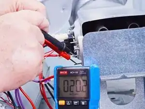
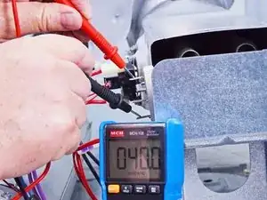
You will first check the resistance between the middle common terminal and each of the element terminals.
-
The resistance should be about 20 ohms (Ω). If the resistance is less than 18 Ω, or greater than 25 Ω, you should replace the element.
-
-
-
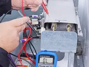
Check the resistance between the top and bottom terminals.
-
Check resistance from the middle terminal to the heater housing.
-
-
-
The next four steps show how to disconnect and remove the hi-limit thermostat and inlet thermistor.
-
-
-
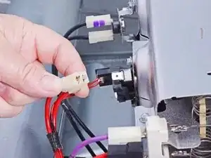
Pull the spade connectors straight off to disconnect the hi-limit thermostat portion of the hi-limit thermostat/inlet thermistor unit.
-
-
-
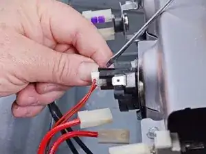
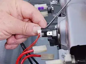
Free the inlet thermistor connector by lifting the black locking tab with a small flathead screwdriver or spudger.
-
Once freed, pull the connector straight out to disconnect the inlet thermistor.
-
-
-
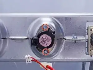
Use a 1/4 inch nut driver to remove the two 12.8 mm long sheet metal screws securing the hi-limit thermostat/inlet thermistor unit.
-
-
-
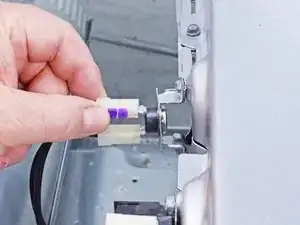
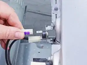
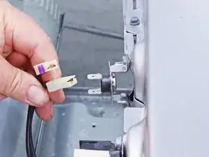
Pull the two thermal cutoff switch spade connectors straight out of their slots to disconnect them.
-
-
-
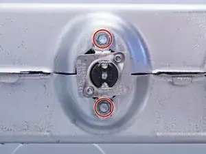
Use a 1/4 inch nut driver to remove the two 12.8 mm-length sheet metal screws securing the thermal cutoff switch.
-
-
-
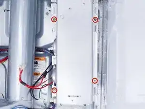
Use a 1/4 inch nut driver to remove the four 12.8 mm‑long sheet metal screws securing the heater housing cover.
-
-
-
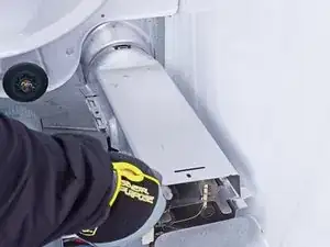
Lift the front of the heater housing cover to release the tabs securing it to the inlet housing pipe.
-
Remove the heater housing cover.
-
-
-
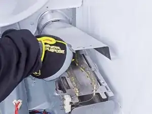
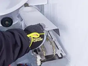
Lift the heating element out of the slots in the lower part of the heater housing.
-
Remove the heating element.
-
To reassemble your device, follow these instructions in reverse order.
Repair didn’t go as planned? Ask our Answers community for help.
