Introduction
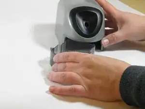
If your pencil sharpener is not turning on when you insert a pencil, you may have a faulty sensor wire. See our troubleshooting guide for more information on this problem. If the problem is your sensor wire, then follow these steps to replace the it. This guide may require some soldering to complete. For more tips and information on soldering see iFixit's soldering guide.
Tools
-
-
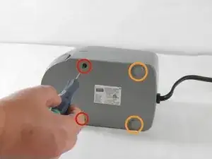
Using a Phillips00 screwdriver, remove the two front 11.6mm screws.
-
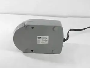
Using the plastic opening tool, remove the back plastic feet.
-
After removing the back plastic feet, using a Phillips 00 screwdriver, remove the two back 11.6mm screws.
-
-
-
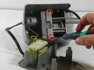
Using a Phillips00 screwdriver, remove two 8.9mm flat edge screws from the top section of the top panel.
-
-
-
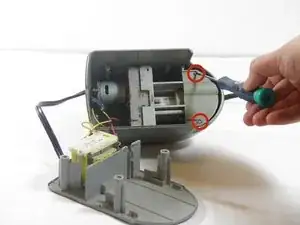
Using a Phillips00 screwdriver, remove two 10.3mm screws from the middle section of the top panel.
-
-
-
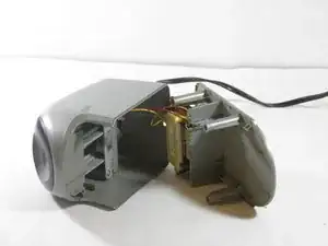
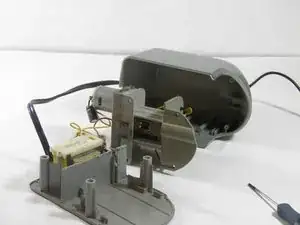
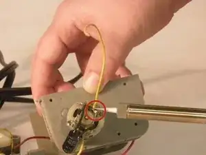
Orient the top panel so the sensor wire's electrical connection is visible.
-
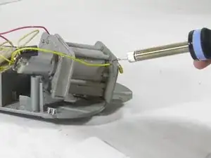
Using a soldering iron, de-solder the sensor wire from the sensor bracket. Be careful to avoid melting the plastic components while soldering.
-
To reassemble your device, follow these instructions in reverse order.
One comment
The yellow wire shown in the above should be tested for continuity before unsoldering. If it’s ok, try the following:
1. Check if there is continuity across the AC power prongs using an ohmmeter. If not, the transformer is bad. That was my problem.
2. Check that the pencil actuated switch closes properly when the pencil is inserted, using an ohmmeter. Clean the contacts if necessary.
3. Check that the small shaving tray safety switch closes when the tray is inserted. It’s actuated by a tab on the R rear of the tray.
4. Apply 12V (AC or DC) to the two yellow wires. If the motor runs, the diodes and motor are ok.
5. Apply 12 VDC to the motor directly, using the two terminals that the black capacitor is attached to. Make sure to attach the negative side as marked on the capacitor, or you might blow the diodes. Use a power source that can supply at least one amp.
I will gladly donate my unit with working motor and good gearbox to anyone that asks. Add a w in front of wayde@hotmail.com
Wayde -
