Introduction

  1. cAa5OS6HCtguGN2W
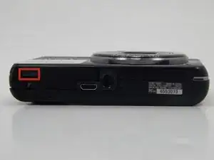
    • Open the flap indicated to allow access to the battery slot.

    • The gray switch indicated has to be moved to the right in order to release the flap.

  2. 31ac6P5PuoUThv44
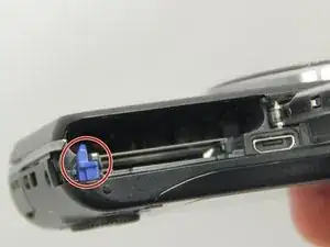
    • If the old battery is still in the slot, then make sure the camera is turned off prior to removal.

    • If there is a battery currently in the slot, remove by first pulling downwards on the blue component. This will allow you to remove the battery from the slot.

    Be careful, i got an electrical shock even after removing the battery when i touched the inner case. i guess, you have to wait some time for static electricity to disapear

    Timm von der Mehden -

  3. vDIFPEsBJY2NUIVr
    vDIFPEsBJY2NUIVr
    wOlZPgZpydDPJV4b
    PFsHC2qQpg35EHs6
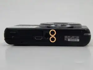
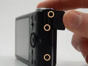
    • Remove all of the 1mm screws using a Philips #000 Screwdriver.

    • Remover the rest of the screws (2mm) from the camera covers using a Phillips #000 Screwdriver.

  4. IRudCFSqG5UowNAY
    IRudCFSqG5UowNAY
    xZAH2lbJUKNHRukX
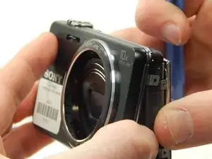
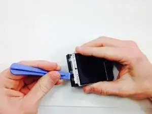
    • Use the plastic opening tool to gently remove the front and back plates of the camera.

  5. JtLsABVYMTEpIMlv
    JtLsABVYMTEpIMlv
    oExtYuqH5CgVIvaN
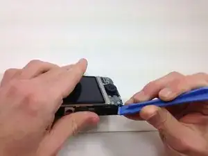
    • Use a plastic opening tool to gently release the two indicated tabs.

  6. Pull up on the lower end of the plate. Lift so the plate is high enough that the marked bump is not holding it in place.
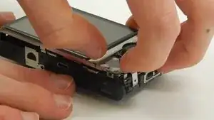
    • Pull up on the lower end of the plate. Lift so the plate is high enough that the marked bump is not holding it in place.

    • Pull away from the camera at the end of the metal plate with the blue circuits to then remove the plate from the rest of the camera.

    • For help with this step, refer to the video.

  7. YNbZIkAcONLTRajF
    YNbZIkAcONLTRajF
    KmeIUHJteFtQDWrJ
    vjDgeXKnlMraMc61
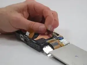
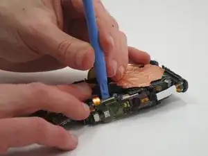
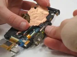
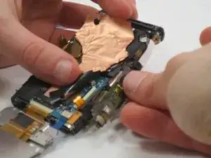
    • Peel back the copper cover and black tape from the motherboard to reveal the connection port.

    • Using the plastic opening tool, release the black bar on the connection port so that the bar is vertical.

    • Pull the tab out.

  8. RGGVBVFZq1US1q4b
    • Pull back on the case, then pull the entire tab out from the case.

  9. uOQwNMy4ZNsHfILL
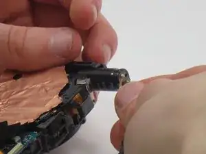
    • Solder the 4 marked nodes and the remove the flash bulb from the sheet.

    • For help on soldering, refer to this Guide.

Conclusion

To reassemble your device, follow these instructions in reverse order.
Matthew

Member since: 19/03/15

583 Reputation

0 comments