Introduction

This repair will solve any problems related to flash malfunctions. For example if the flash is not responding or the flash is not as bright as it should be, this repair will fix these issues.

  1. iYmKV56NCqGmeXBZ
    iYmKV56NCqGmeXBZ
    K1dqPsOQVLeqbSST
    ZC5WYXZgQGLOJS5o
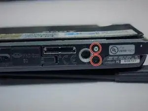
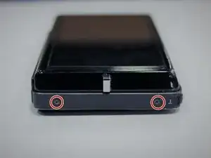
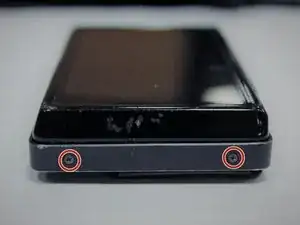
    • Use a Phillips #0 screwdriver to unscrew the six 2mm screws on the outer case of the camera.

    • If there is a battery or SD card inside remove before beginning the process.

  2. Q2Q4PhRBXoBPSCCn
    Q2Q4PhRBXoBPSCCn
    vwUPWYGscFcGBGTh
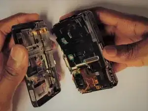
    • Use your hands or a Spudger to Pull off the front cover of the camera.

    • If the casing is not coming apart easily, do not force it.

  3. W65PVrCX1NiZPd1L
    • Remove the protective black cover layer with your hands and set it aside.

    • The use of tweezers may be necessary if the cover is difficult to remove.

  4. FPOCEuSnXEkaCE2b
    FPOCEuSnXEkaCE2b
    wNVbT3hWtW53Khxb
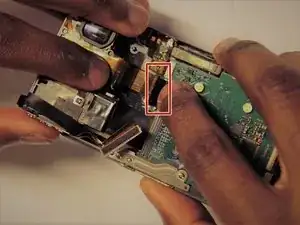
    • The ZIF connector can be removed by flipping the small black holder into the upright position and then sliding the ribbon cable out carefully.

    • Once this has been done, use tweezers to unplug the flat topped connector for the lens’ circuit board from the motherboard.

    • DO NOT force the ribbon cables or they will rip.

    • Refer to the (Recognizing & Disconnecting Cable Connectors) page for assistance.

  5. fiG1O5UScilxRBEe
    fiG1O5UScilxRBEe
    xYPpMB654XD5uEVV
    lVC2xfHsywkQTOSQ
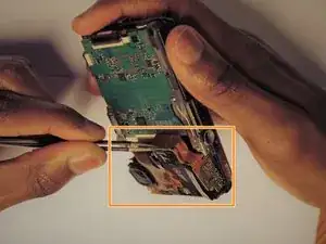
    • Remove the two screws for the metal plate on the bottom.

    • Detach the no fuse ribbon cables by sliding them out.

    • Detach the ZIF connector cables by flipping the small black holder in an upright position and then sliding the cable out carefully.

    • Remove ribbons slowly and carefully or they WILL rip.

    • Screws are of Phillips type, head size Y0 and 0.3 mm in length.

  6. kA4HBcT5DBiuEMlU
    kA4HBcT5DBiuEMlU
    DZN4uLfAAyaeT2Vh
    utfbG1Ifv2emLH3J
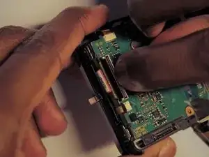
    • Carefully remove the Memory card circuit board. You will then be able to see the flash with the capacitors connected.

    • Using tweezers, carefully remove the components. They are all connected together.

    • The circuit board should come out with little force. If it does not, make sure all connections are disconnected.

Conclusion

To reassemble your device, follow these instructions in reverse order.
Yegor Shea

Member since: 26/03/17

301 Reputation

0 comments