Introduction

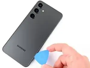
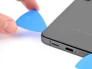
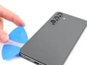
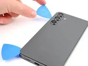
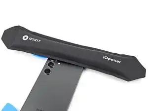
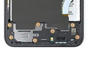
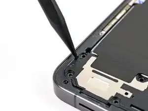
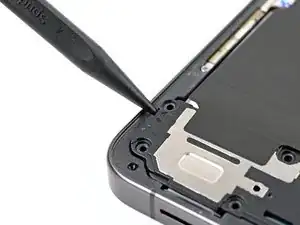
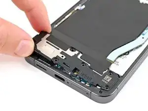
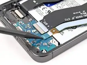
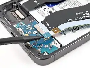
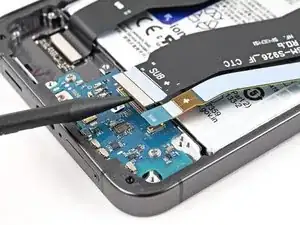
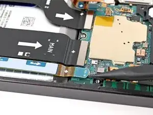
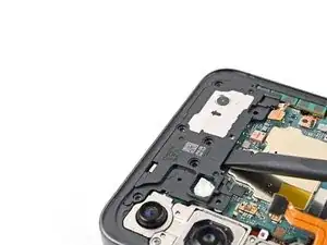
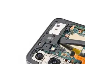
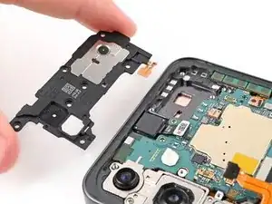
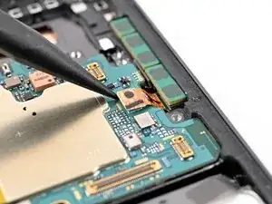
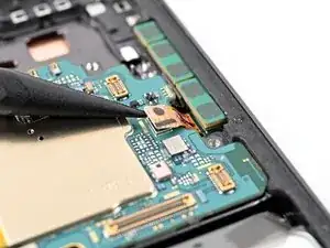
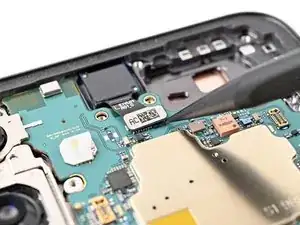
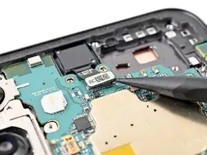
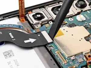
Use this guide to replace the motherboard in your Samsung Galaxy S24+.

  1. 6AgRnQEJGkWJopoM
    6AgRnQEJGkWJopoM
    nVbWCsJDfJdEboHs
    • Allow your phone's battery to drain below 25%, as a charged lithium-ion battery is a potential safety hazard. If your battery is swollen, take appropriate precautions.

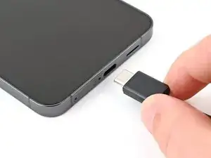
    • Unplug any cables from your phone.

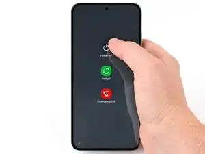
    • Hold the side key and the volume down button, then select "Power off" to turn off your phone.

  2. 5eRL4yBZkj1sYxRK
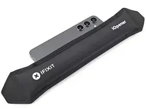
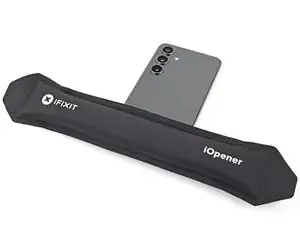
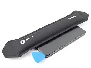
    • Heat an iOpener and apply it to the right edge of the back cover for two minutes.

    • A hair dryer, heat gun, or hot plate may also be used, but be careful not to overheat the phone—the display and internal battery are susceptible to heat damage.

  3. QyYOUCUNB1FtTTGM
    QyYOUCUNB1FtTTGM
    SAgIYSbKUKbJd6Bq
    felvvSjTAp33MUVh
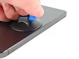
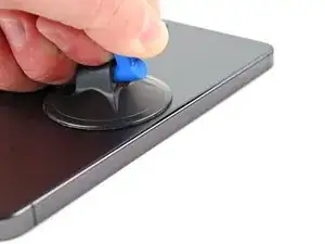
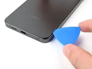
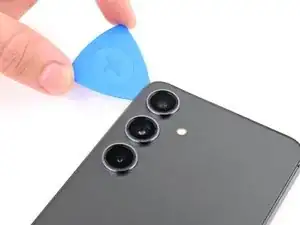
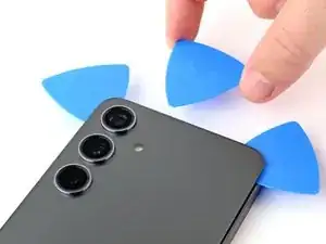
    • Apply a suction handle to the back cover, as close to the center of the right edge as possible.

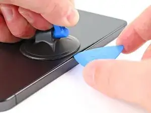
    • Pull up on the suction handle with strong, steady force to create a gap between the cover and the frame.

    • If you have trouble creating a gap, apply more heat to further soften the adhesive. Follow the iOpener instructions to avoid overheating.

    • Insert an opening pick into the gap.

  4. 6AUshiQEBtFPOQII
    6AUshiQEBtFPOQII
    EaORStQ2VxeDTKrF
    JpI5rhPxSvVqSkXB
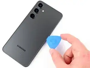
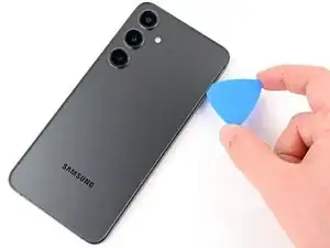
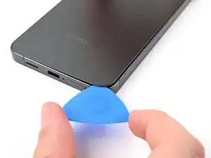
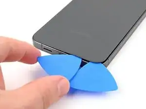
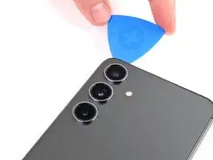
    • Slide the pick back and forth along the right edge to separate the adhesive.

    • Leave the pick inserted near the bottom right corner to prevent the adhesive from resealing.

  5. L1ENIMDPABDnABS3
    • Apply a heated iOpener to the bottom edge of the back cover for two minutes.

  6. idITKmwGtZVg3idl
    idITKmwGtZVg3idl
    MjKKulxNM66eE1oB
    • Rotate the opening pick around the bottom right corner to separate the adhesive.

  7. lCqiRYW6KDjAEGdf
    lCqiRYW6KDjAEGdf
    ZLR4XAHy4FlrDcfB
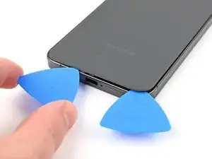
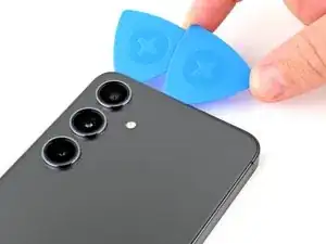
    • Insert a second pick at the bottom right corner.

    • Slide the opening pick to the bottom left corner to separate the adhesive.

    • Leave the pick in the bottom left corner to prevent the adhesive from resealing.

  8. JGgjuiFO6YqkXWyK
    • Apply a heated iOpener to the left edge of the back cover for two minutes.

  9. RrVkJcXggY6Ken61
    RrVkJcXggY6Ken61
    3Hssu3VqCEqogZH1
    • Rotate the opening pick around the bottom left corner to separate the adhesive.

  10. wWnpDobb3VdUbYUV
    wWnpDobb3VdUbYUV
    foZM3pnNOQFxHOXj
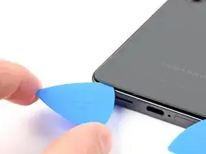
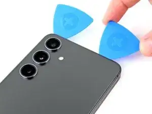
    • Insert a third opening pick at the bottom left corner.

    • Slide the pick toward the top left corner to separate the adhesive.

    • Leave the pick near the top left corner to prevent the adhesive from resealing.

  11. dduGuwroO54TGkYt
    • Apply a heated iOpener to the top edge of the back cover for two minutes.

  12. V32G1Pv3fJMAmjdS
    V32G1Pv3fJMAmjdS
    UVYSQA5knGJcuxRS
    • Rotate the opening pick around the top left corner to separate the adhesive.

  13. KDAL6lNUC5SLWKbb
    KDAL6lNUC5SLWKbb
    fQXZcODUF4u6ETNA
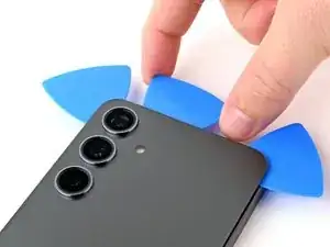
    • Insert a fourth opening pick at the top left corner.

    • Slide the pick toward the top right corner to separate the adhesive.

    • Leave the pick near the top right corner to prevent the adhesive from resealing.

  14. B52Q5qAAMJaZFGB5
    B52Q5qAAMJaZFGB5
    eUEcTvHfTDpQYtti
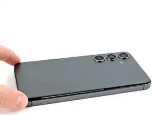
    • There's a square of adhesive around the rear microphone, just above the flash.

    • Line up the tip of an opening pick with the flash.

    • Slide the opening pick under the top of the back cover until you feel it start to snag on the adhesive.

    • Keep sliding the pick toward the bottom of the phone while gently lifting the cover until the cover is free of the adhesive.

  15. KY4YWgdiIEUjakmj
    KY4YWgdiIEUjakmj
    ShJodCQuApCQtGoh
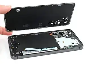
    • Grab and remove the back cover.

    • If the back cover is not lifting easily, use an opening pick to separate any adhesive that may have resealed.

    • During reassembly:

    • This is a good point to power on your phone and test all functions before sealing it up. Be sure to power your phone back down completely before you continue working.

    • Retaining water resistance after the repair will depend on how well you reapply the back cover adhesive, but your device will lose its IP (Ingress Protection) rating.

    • Use tweezers or your fingers to remove all adhesive from the back cover and the phone. Use heat or isopropyl alcohol (90% or greater) and a coffee filter or lint-free cloth if you're having trouble removing the adhesive.

    • If you're using custom-cut adhesives, follow this guide.

  16. RlZnZMDYR1PC2EDt
    RlZnZMDYR1PC2EDt
    2Ce3LtVWh3y1DSxv
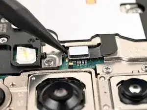
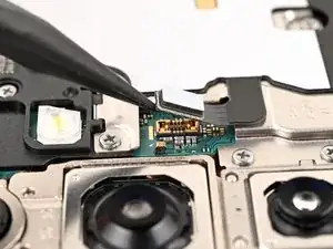
    • Use a spudger to pry up and disconnect the wireless charging coil press connector from the motherboard.

    • There's an arrow printed on the board near each press connector that indicates the recommended prying location.

    • To reconnect press connectors, align the connector carefully over its socket and press down with your fingertip—first on one side, then the other—until it clicks into place. Don't try to force the connector into place. If you're having trouble, reposition it and try again.

  17. QZlIXunjdUTfNKBR
    QZlIXunjdUTfNKBR
    uv6WqTZQDIJRSEQF
    3pSDt3OGWAjvLHSG
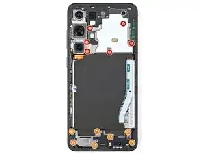
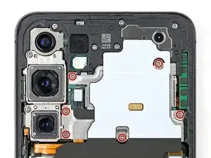
    • Use a Phillips screwdriver to remove the thirteen 3.5 mm‑long screws securing the wireless charging coil and the loudspeaker:

    • Six screws securing the wireless charging coil

    • Seven screws securing the loudspeaker

  18. 5wHtM1tGplD1bURG
    5wHtM1tGplD1bURG
    aOxFKMamFCsbVMeN
    • Insert the point of a spudger in the notch at the top left corner of the loudspeaker, which is marked by an arrow.

    • Pry up to unclip the loudspeaker from the frame.

  19. vWKYPkXMLbJGXEbG
    vWKYPkXMLbJGXEbG
    yE6UOoCBsRbEoTYw
    hkmUwdhvkEorATLf
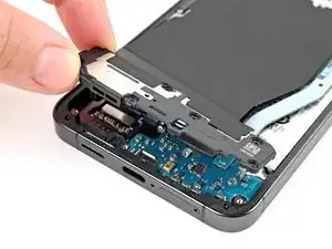
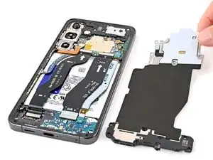
    • Use your fingers to lift the loudspeaker away from the frame.

    • Remove the wireless charging coil and loudspeaker from the frame.

    • During reassembly, press around the edges of the loudspeaker to clip it to the frame before reinserting the screws.

  20. Gql3VUlQEJMNqUbn
    Gql3VUlQEJMNqUbn
    Vb6N2ygAqoZZEjUP
    • Use a spudger to pry up and disconnect the battery press connector.

  21. NAKnW22SDkYGPC4B
    NAKnW22SDkYGPC4B
    tkbvM4RkZrkIE6Zq
    pDR1ICjMY1wrUWdY
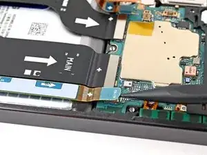
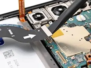
    • Use a spudger to pry up and disconnect both interconnect cable press connectors from the daughterboard.

  22. N2OD2wEE4DD32hfv
    N2OD2wEE4DD32hfv
    l1EUZQE1BWkxCgxJ
    sScyXlJvIVLUsMPt
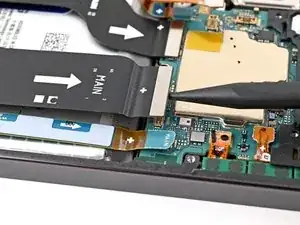
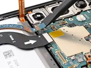
    • Use a spudger to pry up and disconnect both interconnect cable press connectors from the motherboard.

  23. aN4QYj2oUracRjDZ
    aN4QYj2oUracRjDZ
    wQNnIEZCCuq5oXGD
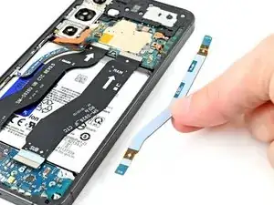
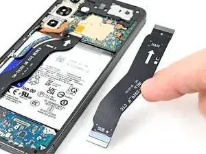
    • Grab and remove the interconnect cables from the phone.

  24. Q2uK4nJxB2D1UQca
    Q2uK4nJxB2D1UQca
    xAtr4DLfT5hnPtVP
    • Use a spudger to pry up and disconnect the earpiece speaker press connector.

  25. P5CsSxRSyrgqVdNV
    P5CsSxRSyrgqVdNV
    ZMvBdfRowgs1OURu
    • Use a Phillips screwdriver to remove the five 3.5 mm‑long screws securing the earpiece speaker.

  26. xHUMtDmQodUAnvKH
    xHUMtDmQodUAnvKH
    VurN5hRy23fEFFJL
    A5mJ6vrrFC6WOOPQ
    • Insert the flat end of a spudger between the bottom edge of the earpiece speaker and the metal plate on the motherboard.

    • Twist the spudger to unclip the earpiece speaker from the frame and remove it.

    • During reassembly, insert the top edge of the earpiece speaker into the frame first before pressing down and clipping it back in.

  27. fmmgRGciaGEfJKJv
    fmmgRGciaGEfJKJv
    YFoTpfPXSZCKUc4h
    • Insert the tip of a spudger under the top left corner of the upper antenna press connector.

    • Do not insert the spudger anywhere else to avoid damaging surface-mounted components.

    • Pry up and disconnect the upper antenna press connector from the motherboard

  28. WrfCMtFV3DbtaLXC
    WrfCMtFV3DbtaLXC
    hTJZJuYDm2ffW6cL
    • Insert the tip of a spudger under the bottom right corner of the front camera press connector.

    • Do not insert the spudger anywhere else to avoid damaging surface-mounted components.

    • Pry up and disconnect the front camera press connector from the motherboard.

  29. GK6RjHagfRj26ruf
    GK6RjHagfRj26ruf
    jufgSG1qYVTdCUB4
    BdSJ2BdFW6VrifB6
    • Use a spudger to pry up and disconnect the display and lower antenna cable press connectors from the motherboard.

  30. NTk12yyEIMaSXQyN
    NTk12yyEIMaSXQyN
    YauAHhIvYdPJALdE
    • Use a Phillips screwdriver to remove the two 3.5 mm‑long screws securing the motherboard.

  31. XDXsAWjIqD4K2eSY
    XDXsAWjIqD4K2eSY
    QGERnI51Y1JQ4HL6
    eqOPCiNtSYNHbSPB
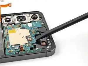
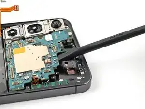
    • Insert the flat end of a spudger between the top edge of the motherboard and the phone frame, in the earpiece speaker cutout.

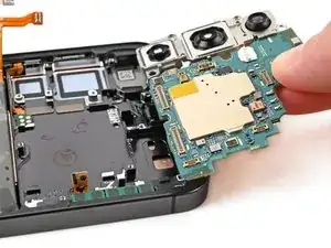
    • Pry against the frame to lift the motherboard out of its slot and remove it.

    • During reassembly, make sure all of the cables are out of the way before placing the motherboard back into the frame.

  32. L6hfdYdRHlirsMsj
    L6hfdYdRHlirsMsj
    IyhZy4PUE12LydD2
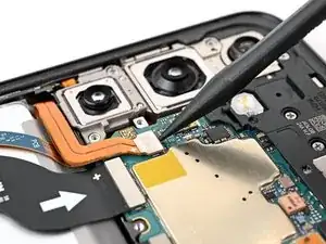
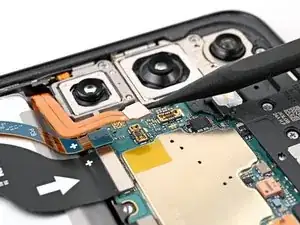
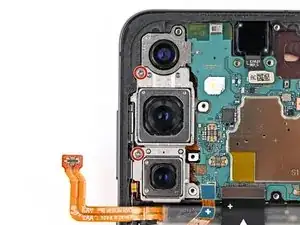
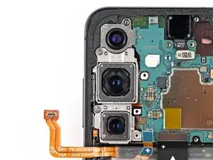
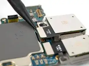
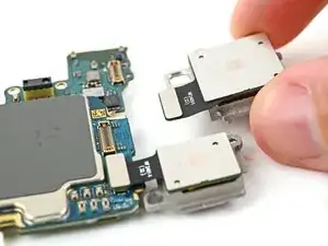
    • The three rear cameras are slotted into each other and should be removed in the following order: ultrawide, main, telephoto.

    • Flip over the motherboard to expose the rear camera press connectors.

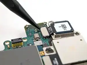
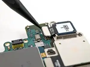
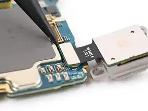
    • Use a spudger to pry up and disconnect the ultrawide camera press connector.

    • The ultrawide camera is the top camera when installed.

  33. etKldRlQxeilRB1y
    etKldRlQxeilRB1y
    NtnkiKZOTNX6MBYV
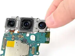
    • The ultrawide camera is hooked into the motherboard with two metal pegs.

    • Slide the pegs on the ultrawide camera out of their holes in the motherboard to remove it.

  34. ZinFBXinHSl2BQFE
    ZinFBXinHSl2BQFE
    cnPquAFKrTDgjZAB
    Ut3sBaBPig2FoLKT
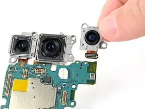
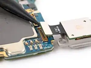
    • Use a spudger to pry up and disconnect the main camera press connector.

    • The main camera is in the middle.

    • Lift the main camera off the motherboard and remove it.

  35. FLG3VqETCHD5LrwC
    FLG3VqETCHD5LrwC
    filY41GJCqZflaDo
    Ho2dOpfhX42NvBLy
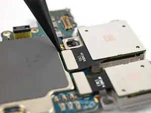
    • Use a spudger to pry up and disconnect the telephoto camera press connector.

    • The telephoto camera is the bottom camera when installed.

    • Lift the telephoto camera off the motherboard and remove it.

    • During reassembly, install the rear cameras in the following order so they slot into each other properly:

    • Telephoto (small camera with metal back)

    • Main (large camera with metal back)

    • Ultrawide (plastic back)

  36. SZaDJC5fxv5tmTgh
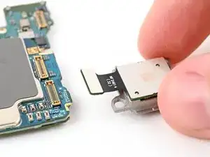
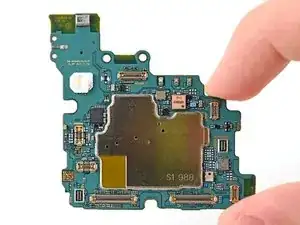
    • You're now left with the motherboard for replacement.

Conclusion

To reassemble your device, follow these instructions in reverse order.

Repair didn’t go as planned? Try some basic troubleshooting, or ask our Answers community for help.

Take your e-waste to an R2 or e-Stewards certified recycler.
Spencer Pennington

Member since: 09/09/23

9416 Reputation

0 comments