Introduction

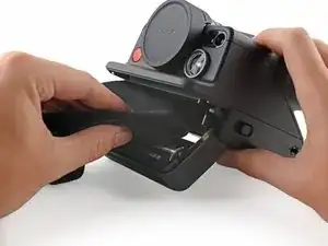
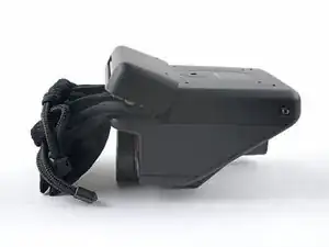
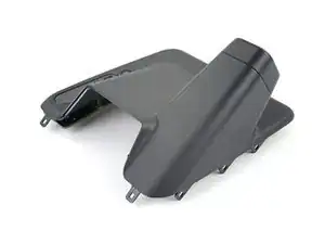
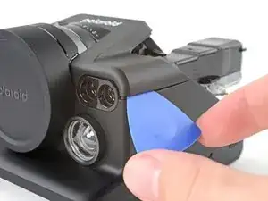
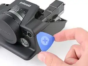
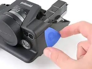
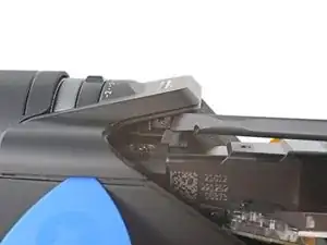
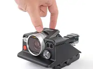
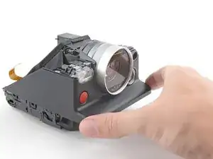
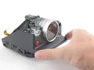
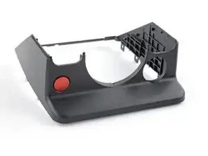
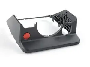
Use this guide to replace a cracked or damaged front cover in your Polaroid I-2 camera.

The clips securing the plastic covers are strong and require significant prying. Don't use metal tools to avoid marring the plastic.

  1. jNIhBLYAKUEFRSwD
    jNIhBLYAKUEFRSwD
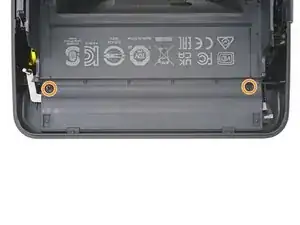
    hiU1snQqEYDaCHUP
    cJCgTagQWCE2Wpnh
    • If you have any film left, take some photos and remove the cartridge! Disassembly will expose the film and damage it.

    • Before you begin:

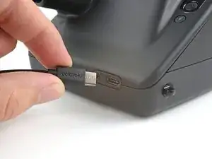
    • Power down and unplug your camera.

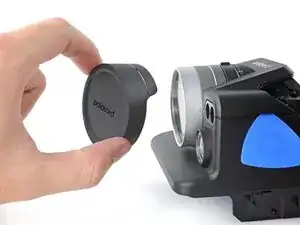
    • Put on the lens cap to avoid scratching your lens during disassembly.

  2. lE5jChZKKoyRbTuu
    lE5jChZKKoyRbTuu
    XEQl4IiUMLNJxpx5
    • In the following steps, "left" and "right" are written from the perspective of using the camera—or when the lens is facing away from you.

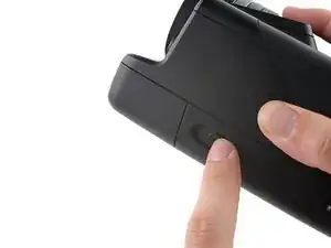
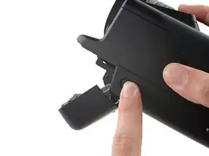
    • Use the latch on the left side of the camera to open the film door.

  3. XJSsoywxEUQDnh1Y
    XJSsoywxEUQDnh1Y
    abBjlAsjRMJ1lN4y
    axYCAxjmaGhGArjh
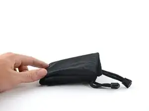
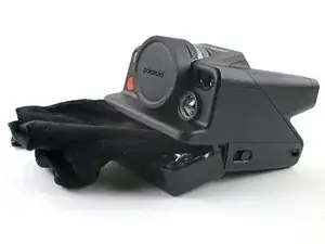
    • Fold a piece of cloth or napkin (or the included bag) into a small square.

    • Insert the cloth into the film compartment far enough to block the film door from closing during disassembly.

  4. DNxvJhpInTBBAxlK
    DNxvJhpInTBBAxlK
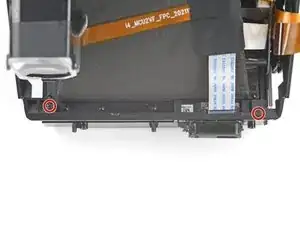
    BZZY3jqQGNhMXRHw
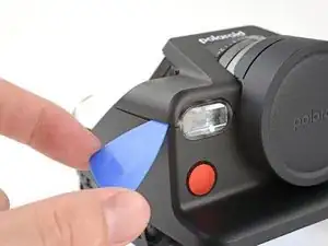
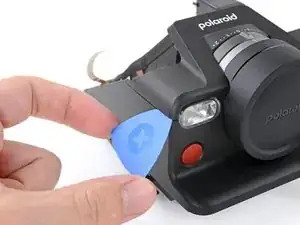
    IMY4fWiDNrgCl4jg
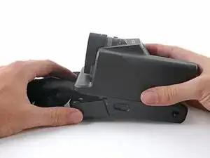
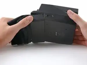
    • Flip the camera over, making sure the cloth stays lodged in the film compartment.

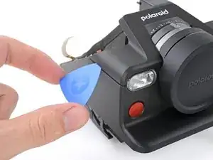
  5. YFDmHemcEMHSbxoJ
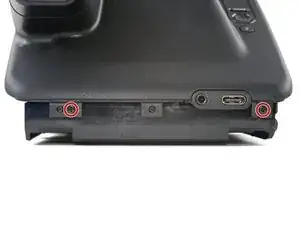
    • Use a Phillips screwdriver to remove the four 3.9 mm-long screws securing the bottom cover.

  6. Y1yLiJdn45vlBDwY
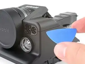
    Y1yLiJdn45vlBDwY
    RISilDSL2lNBawpM
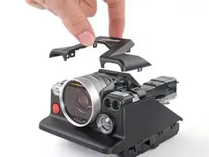
    KRIL5ZtfNNTubZy3
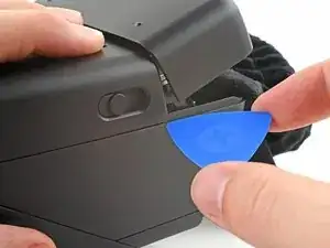
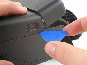
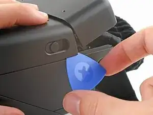
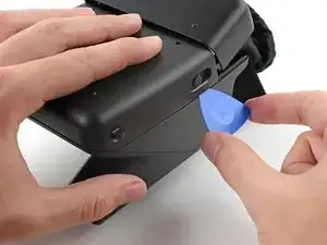
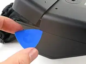
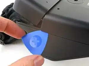
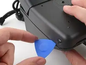
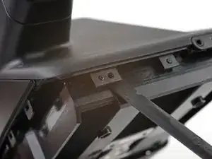
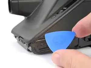
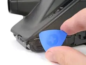
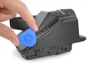
    • Insert the tip of an opening pick under the top left corner of the bottom cover, near the slider button.

    • Tilt the pick up and push to position the pick between the bottom and front covers.

  7. aoDAHGfLBuJeKjQa
    aoDAHGfLBuJeKjQa
    o2Kxt4OGfXrBTRcf
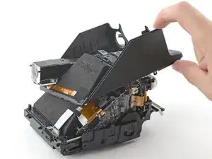
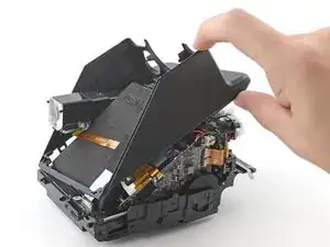
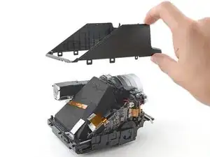
    PXgBLiJ6gflDtque
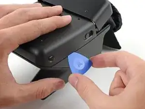
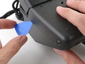
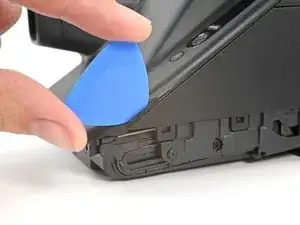
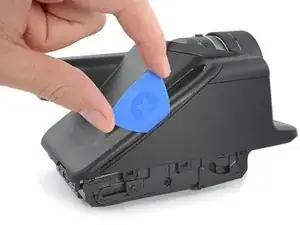
    • Slide the opening pick toward the rear of the camera to release the clips along the left edge.

    • Leave the opening pick at the bottom left corner to prevent the clips from resecuring.

  8. UBcDiHe3HWoqWFTn
    UBcDiHe3HWoqWFTn
    VeYqsFT5OQ1AQyBD
    QFOQEAuNIQOyTUlx
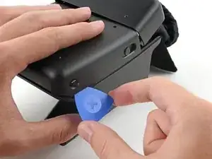
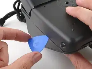
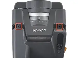
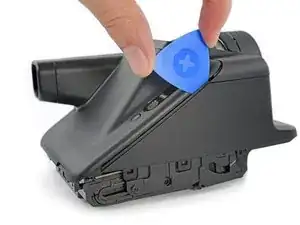
    • Insert the tip of a second opening pick under the top right corner of the bottom cover.

    • Tilt the pick up and push to position the pick between the bottom and front covers.

  9. qNMWfmfuiXgyPol6
    qNMWfmfuiXgyPol6
    lRtGYOY2H2GoKN2v
    KaXR4AEEsyjysvsI
    • Slide the opening pick toward the rear of the camera to release the clips along the right edge.

  10. bYAOJ56UdAASmvOR
    bYAOJ56UdAASmvOR
    GpLM3VOaLJTjaPtw
    jTeE41iGFbyDoRkN
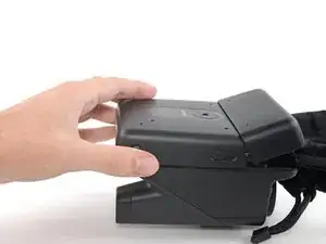
    • At this point, the bottom cover clips should be released. If not, slide an opening pick along the perimeter of the back cover to release any remaining clips.

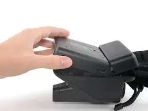
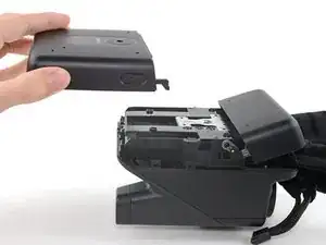
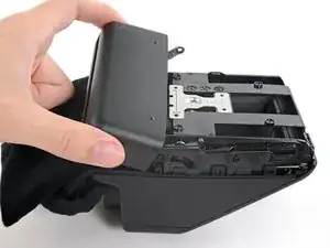
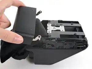
    • Tilt the back of the bottom cover upward and pull it away from the camera, making sure to thread the film door lever from its recess.

    • Remove the back cover.

    • During reassembly, insert the film door lever into its recess before aligning the bottom cover and pressing it into place to secure its clips.

  11. Rq2EgUT1DkWBLF6e
    Rq2EgUT1DkWBLF6e
    LoBYaPMtNFNxIYuC
    4UGMSvuKTRBUG3vT
    • Insert the flat end of a spudger between the film door's left hinge and the frame.

    • Twist the spudger to separate the rubber hinge grommet from its peg in the frame.

    • Pull the film door towards the front of the camera to completely disconnect its left hinge.

  12. tOjgWXcWGr5X6uh4
    tOjgWXcWGr5X6uh4
    N5CJIvVwhKp1jVEG
    cElveVjHGvQ1MTVO
    • Tilt the left edge of the film door up to separate the left hinge's rubber grommet.

    • Remove the film door.

    • At this point, you can remove the cloth blocker from under the print roller.

    • During reassembly, hook the left hinge on its post and push the right hinge over its post until it snaps into place.

  13. tHDfEaBQlEZ2UMtT
    • Use a Phillips screwdriver to remove the two 3.9 mm-long screws securing the back cover.

  14. MWpXSFTDHtvp1wYC
    MWpXSFTDHtvp1wYC
    L1KJSD25WEnTQFZx
    mbIvV3SNWSQUpP2Y
    • There are two alignment pegs along the bottom edge of the back cover.

    • Insert a spudger between the frame and the alignment hole on the back cover.

    • Twist the spudger to lift the back cover off of the alignment peg.

    • Repeat for the second alignment peg.

  15. XN1VAO6FPOmhBwWK
    XN1VAO6FPOmhBwWK
    iLWBd4HxNQOatUFZ
    TKOpYKKYYN6POkIM
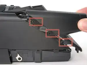
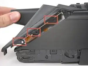
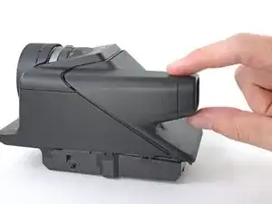
    • There are eight large clips that secure the back cover. The next four steps show how to release them.

    • These clips are very strong and require significant force to release.

    • The procedure to release the clips is tricky and will require time and patience to perform correctly.

  16. oUIiHhU16LDiblrX
    oUIiHhU16LDiblrX
    tdvKXDpRjOxLU2rU
    RO2Un3oavIWJ1wFr
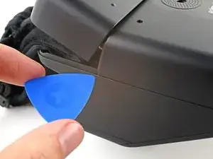
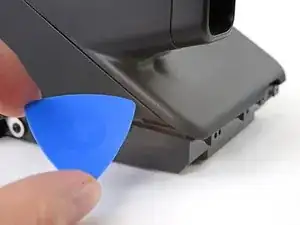
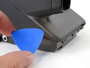
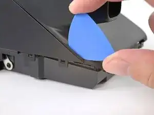
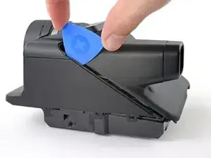
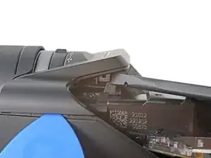
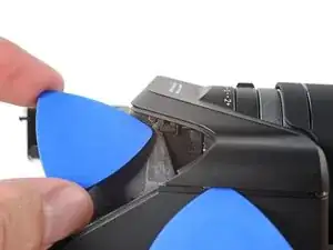
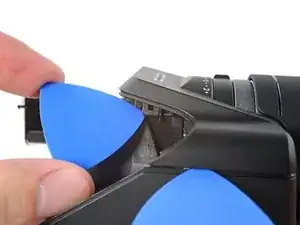
    • Releasing the clips requires getting a tool between the covered "thin" edge of the front cover and the clips themselves.

    • Angle an opening pick upward and insert it at the gap where the bottom right corner of the back cover meets the triangular tip of the front cover’s right edge.

    • Push the pick up to get it above the overhanging lip in the back cover.

    • You'll see the plastic warp a little. This is normal.

    • While pushing upward, slowly rotate the pick towards the left edge of the camera until it's under the front cover.

    • The pick can slip out easily, so this may take a few tries.

  17. lwPfPwnhRGtRyP3G
    lwPfPwnhRGtRyP3G
    ijgBN1k4vWCck3NE
    xJxlLQuPtQXAGB3C
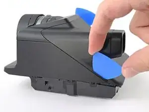
    • While pushing the pick downward, slide it all the way up the right edge to release the clips.

    • Keep the pick as upright as possible while sliding to avoid hitting the clips.

    • The plastic in the lip of the back cover will warp. This is normal.

    • Leave the pick at the top corner before continuing to prevent the clips from resecuring.

  18. ZSYMW5YfJE1YivDn
    ZSYMW5YfJE1YivDn
    ErSdNa6QJlvhqHW4
    m4HwsiWvoqKomZje
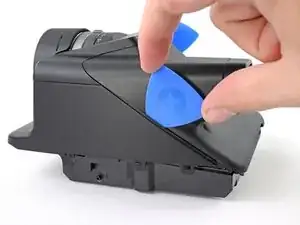
    • Angle a second opening pick upward and insert it at the gap where the bottom left corner of the back cover meets the triangular tip of the front cover’s left edge.

    • Push the pick up to get it above the overhanging lip in the back cover.

    • You'll see the plastic warp a little. This is normal.

    • While pushing upward, slowly rotate the pick towards the right edge of the camera until it's under the front cover.

    • The pick can slip out easily, so this may take a few tries.

  19. FN5hikMX4OQD3MDk
    FN5hikMX4OQD3MDk
    NNWnB12HiNOEnZP4
    gIwMZueMiRgpmKy6
    • While pushing the pick downward, slide it all the way up the left edge to release the remaining clips.

    • Keep the pick as upright as possible while sliding to avoid hitting the clips.

    • The plastic in the lip of the back cover will warp. This is normal.

  20. kO3hvHefdFYHNfll
    kO3hvHefdFYHNfll
    ODajiiSGHa4pbjpQ
    LiQ4Bb1EvrETdcEJ
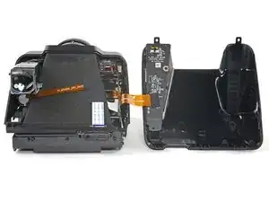
    • Don't try to pull the back cover off just yet, as it's still connected by a cable.

    • At this point, the back cover should feel loose. If any parts still feel connected, repeat the last four steps until all the clips release.

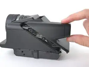
    • Pull the back cover off the camera and rotate it over the right edge to expose the flex cable.

    • During reassembly, make sure the the flex cable isn't caught between the covers before re‑engaging the clips.

  21. lpOnaDBUU6inXWCK
    lpOnaDBUU6inXWCK
    n1ooA3IBvRKsFieU
    4HEEfooMiVn3pKAP
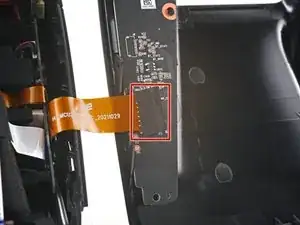
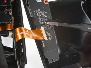
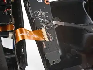
    • Use tweezers to peel off the tape covering the interconnect cable ZIF connector on the control board.

    • Set the tape aside. You'll reuse it during reassembly.

  22. VS2FrbSMIIFIPoEy
    VS2FrbSMIIFIPoEy
    mVnkGYDhPBVEHPJm
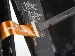
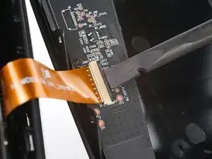
    • Use the flat end of a spudger to lift up the locking flap on the control board ZIF connector.

  23. i3oQNCwhUa5CCk6p
    i3oQNCwhUa5CCk6p
    VpeUd1x6vYkVEaj1
    Md4jYoyVyDvw1Vi6
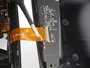
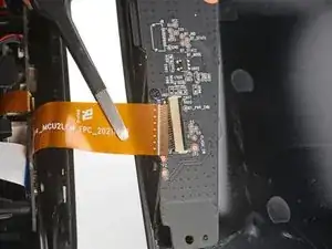
    • Use tweezers to pull the interconnect cable out of its slot in the control board.

    • Remove the back cover.

  24. cNMvHvXTdIbsY4eF
    cNMvHvXTdIbsY4eF
    R1aOZldOWZAeuy1h
    5hS1pBAALZYgKkkE
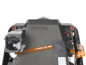
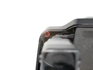
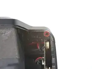
    • Use a Phillips screwdriver to remove the two 3.9 mm-long screws securing the top cover.

  25. fDUYA1IdjGlNgx42
    fDUYA1IdjGlNgx42
    wh6NjUQYKvUmMZPV
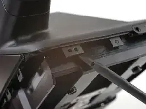
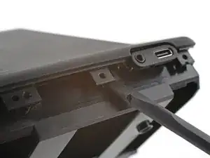
    • The next six steps demonstrate how to release the top cover's clips. These clips can re-engage easily, so you may need to repeat certain steps to release all of the clips.

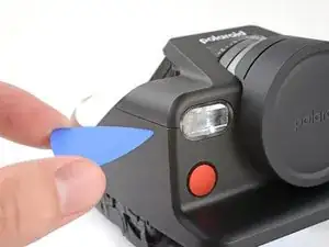
    • Angle an opening pick upward and insert in the gap at the top right corner of the top cover and front cover, next to the flash.

  26. QFVjsV2NCsLdHUyd
    QFVjsV2NCsLdHUyd
    iOR6ZJY4d5NhWdQV
    • Slide the opening pick toward the rear of the camera to release the clips along the right edge.

    • Leave the pick in the gap before continuing to prevent the clips from re‑engaging.

  27. x6isNggqUWHLiUJU
    x6isNggqUWHLiUJU
    ZNZWZKZtgnD4hmAB
    • Angle a second opening pick upward and insert in the gap at the top left corner of the top cover and front cover.

  28. vDYNEs5oxTXr5hw3
    vDYNEs5oxTXr5hw3
    GOPMCIurLUNRlUEq
    • Slide the opening pick toward the rear of the camera to release the clips along the left edge.

    • Leave the pick in the gap before continuing to prevent the clips from re-engaging.

  29. 3qhSoGGdJd1KjdQi
    3qhSoGGdJd1KjdQi
    6DIjOxe3GGmsXGRS
    • Insert the flat end of a spudger between the frame and the top cover's left external clip, above the viewfinder.

    • Twist the spudger to release the clip.

    • If one of the opening picks fall out, don't worry! Continue with the guide as normal.

  30. bBfEfqQgrFmHvkZT
    bBfEfqQgrFmHvkZT
    ZJ2E1F4DYQFhHOHb
    • Insert the tip of an opening pick between the frame and the top cover's right external clip.

    • Pry up to release the clip.

  31. stqLYEDNXWhfBGLL
    • Pull the lens cap off and remove it.

  32. pLoWmiBMCyKpVXmj
    pLoWmiBMCyKpVXmj
    UscWETE3bnDPDJ3D
    • Lift the top cover off the camera and remove it.

    • During reassembly, push the top cover onto the frame until the clips re-engage.

  33. iYbMUSoy34BHcKCU
    iYbMUSoy34BHcKCU
    iZi1MtDwAyFMdqbB
    • Use a Phillips screwdriver to remove the four screws securing the front cover:

    • Two 5.9 mm-long screws along the back edge of the front cover

    • Flip your camera over.

    • Two 3.9 mm-long screws under the front of the camera

  34. g1QHAHeqGEHMfvDh
    g1QHAHeqGEHMfvDh
    On4rBeVEbBueP1dh
    • The clips that secure the front cover are tricky to release. During the removal procedure, you may have to wiggle and bend the plastic to get the clips to release properly.

    • Pull the front cover away from the lens to release the clips along the front edge and slide the viewfinder out of its cutout.

    • You'll hear a "click" and the front cover will be able to move freely.

    • During reassembly, align the viewfinder cutout over the viewfinder lens before pressing the front cover into place and re-engaging the clips.

  35. e6IGffSWkn1BVW42
    e6IGffSWkn1BVW42
    mRTJtBTBCrC3Bwl2
    BkQCaBB1VKyACchT
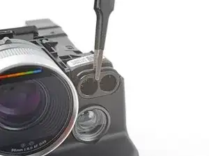
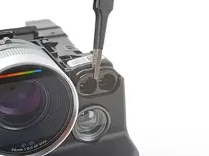
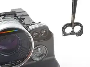
    • The lidar sensor bracket is secured with two alignment pegs that fit into cutouts on the bracket.

    • Use tweezers, or your fingers, to push the lidar sensor bracket toward the lidar sensor and off its alignment pegs.

    • Remove the lidar sensor bracket.

  36. 6jK5qd4Zs35VCv5D
    6jK5qd4Zs35VCv5D
    25BJAQZbC1UeStst
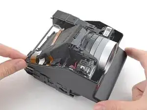
    • Lift the rear of the front cover while pulling the entire cover toward the front of the camera to separate it from its lip under the lens.

    • If you're having trouble, rock the cover side-to-side while pulling.

  37. 3toBp2OEx6kO3WMr
    3toBp2OEx6kO3WMr
    UeeamVRwKCIvSFXn
    FhaSvOcScARJ3srs
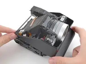
    • Lift the front of the cover over the lens.

    • Slide the front cover toward the rear of the camera until the back edge clears the viewfinder.

  38. DIlMCTltIYGMwXk2
    DIlMCTltIYGMwXk2
    VP6SZGdNFWNk6FDi
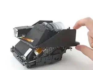
    • Remove the front cover.

    • If you're disassembling further, put the lens cover back on to prevent scratching the lens.

    • At this point, the metal film door lever and spring are at risk of falling out. If they do, follow this guide to reinstall them.

Conclusion

Compare your new replacement part to the original part—you may need to transfer remaining components or remove adhesive backings from the new part before you install it.

To reassemble your device, follow these instructions in reverse order.

Repair didn’t go as planned? Try some basic troubleshooting, or ask our Polaroid I-2 Answers community for help.
Alex Diaz-Kokaisl

Member since: 16/01/22

134278 Reputation

0 comments