Introduction

If your Nexus 7 2nd Generation rear facing camera happens to stop working or is in need of replacement, look no further than this guide. You will need to remove the battery and motherboard in order to access the camera. Also worth noting, the rear facing camera may not come up with the motherboard during removal. The camera is adhered to the front case, so if it isn’t present on the motherboard, look to the recess in the front case. Make sure to attach the camera’s ribbon connector to the motherboard during replacement.

  1. xHPWImtKyPYRU6Qm
    xHPWImtKyPYRU6Qm
    EZf335HVLEPfcfkW
    • Power down your device.

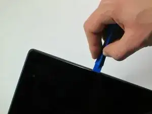
    • Use your plastic opening tool to wedge between the seams around the sides of the device. Pry open each side, one at a time. For some a finger nail may be best. The case comes up quite high to the glass.

    • Do not pry near the USB port at the base of the device as you may crack the rear panel.

    I had a heck of a time doing this, spent ten or twenty minutes carefully prying, and I STILL cracked the case. At least on mine, the case was held in VERY well and required prying pretty much everywhere before it would let go. The tools I bought from iFixit really helped, but still a royal pain to open.

    pacmanmaster -

    a couple of obscure things that might help in opening:

    guitar pick. get a few; they are cheap.

    a prying device made for the sign industry: its called"lil' chizler". I have found that this to be the most helpful opening tool.

    http://www.ebay.com/itm/like/16184595677...

    also

    https://www.qualitylogoproducts.com/trad...

    you can use the broken screen unit to test.

    Len Gorsky -

    Add "remove the sim tray"...

    Iain Lennon -

    I echo the previous - a right royal pain to get the cover off! I started on the right side as seemed to be more give there… iFixit tools helped tho!

    Steven Emery -

    Just for the sake of clarity, I would add that you need to pry between the plastic bezel and the back casing. Not between the glass and bezel. Someone had already tried on the one I worked on and part of the bezel was missing in the top right corner. Made my job easier!

    The best tools for this part are definitely something like the iFixit Jimmy and their opening tool, a few guitar picks and a spudger. Not too difficult once you get the first separation.

    Cool_Breeze -

    I managed to easily crack the screen, guess I’ll have to order a new one and “try” to put it in, in addition to the original job of replacing a dead battery on Nexus 7 2013..ahhhhhh, slow learner…

    Gary Stamey -

    Opened the case for the first time. It took me a while to find any gaps, but I found that the easy way to begin was using your fingernail to get into the sides. The middle left and middle right seemed a lot easier to…slip a nail in compared to the rest of the case, especially the corners and the top and bottom. With a small opening on both sides I used the opening tool to increase the gaps while using a couple of guitar picks to prop up the device against the back case. With most of the sides exposed, I worked on the bottom (create opening, leave a guitar pick to keep that part open, use the opening tool to get the rest out), and the opening was pretty much complete.

    So far only the corners of the back case showed small cracks and my screen was pretty much unscathed.

    Nam Lam -

    This method worked best for me! Start opening on the middle left and right sides, then prop them open with guitar picks and use to the opening tool (carefully) prying up several times moving away from the middle towards the corners to pop off the back casing.

    Frank's VR -

  2. RcOxAHLDxh4N6FCW
    • Work fingers around the seam between device and back cover. Use your plastic opening tool and fingers to separate each side until device and back cover are completely apart.

    • Be careful around the corners. The body of the device can be fragile.

    I did two of these. The first was a WIFI model that the earphone plug had become intermittant (just needed to resolder the connections.) The second an LTE version that the battery had gone bad and swelled to about 3 times the size.

    The swollen battery had pushed the glass free of the upper mount, and made the entire thing extremely tight.

    The WIFI one came apart easily like described.

    The LTE one (with the swollen battery) required a lot more care and a lot more force/damage to get into the gap between the two plastic pieces. (I did the wifi one first, so I could easily tell the difference.

    So depending on your situation...it may not be easy to separate the pieces...but remmber, the thin glass is sitting on one piece of plastic, the gap is between that piece of plastic and the back panel...a darker shiny black plastic is the top piece, a slightly lighter duller black plastic is the back panel...of course the glass is ALSO black...so good luck.

    dick -

  3. pJQvct2ghNT3Ntwt
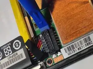
    • Insert the plastic opening tool under the side edge of the battery connector, and gently pry upward to disconnect it.

    THIS should be the first cable to disconnect. Always remove power first!

    dave -

    We moved this step to be fist, thanks for the edit!

    Sam Goldheart -

  4. dMEoF2y1nSFjKRYR
    dMEoF2y1nSFjKRYR
    qXlvkuABnDJCyrvr
    IdKiTLJfjdHgPDDe
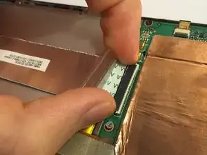
    • Use the flat end of a spudger or your fingernail to flip up the clear protective flap on the ribbon cable ZIF socket.

    • Using the flat end of a spudger or your fingernail, flip up the thin portion of the connector (the white part, opposite of the side where the cable inserts) to release the cable from its socket.

    • DO NOT PRY the socket on the side where the cable inserts, or you may break the entire socket off the motherboard.

    • Slide the cable out of the ZIF socket.

    • For more info on how to disconnect ZIF connectors, check out the Recognizing & Disconnecting Cable Connectors guide.

    Flip up on the WHITE part, facing away from the cable. I sort of struggled with this part, but fortunately didn't do any serious damage.

    yuguoxiong -

    This is the correct way to do it. Flipping up the white part is what you have to do. I tried flipping up the black part and some of it broke off.

    Ryan -

    I found that I had to flip up on the black part here. I broke a section of the white trying to flip it up.

    pattylanter -

    This comment saved me on this step. Indeed the secret is to flip up the black part of the connector, located opposite the side where the cable inserts.

    Hannah Cirimele -

    This is wrong, these comments should be deleted so as to not confuse more people.

    Jeff Andrews -

    It's possible there's more than one color variation in production on these Nexus 7 ZIF sockets. To complicate matters, it looks like the guide's original author/photographer may have simply yanked the ribbon cable out without opening the socket, so there's very little visual clue here as to which is the right section to flip up. Based on these photos, I'd say Hannah's tip is probably correct—you want to flip up the thinner portion of the socket, opposite the cable (regardless of its color scheme). If someone who has successfully completed this step could supply a better photo, that would be super helpful!

    Jeff Suovanen -

    I revised the text so there's no long any mention of the coloration of the socket.

    Jeff Suovanen -

    I believe I broke the ZIF attached to the mobo at this step; is there any other way to reconnect it during reassembly or will I require a new mobo?

    Neil Reed -

    This was my first time with this kind of ZIF socket and found these instructions/pictures ambiguous. In hindsight I see what was being described (actually used the replacement daughterboard as my guide). May I suggest this phrasing:

    The ZIF clamp hinges on the side opposite of where the cable in inserted. Using the flat end of a spudger or your fingernail, flip the thin portion of the connector up and away from the insertion side of the connector.

    charles fineman -

    Correction of Charles' Oct comment: The ZIF clamp hinges on the same side as the cable is inserted, the side towards the battery. The cable runs over the battery and into the thick connector, with contacts both on the side closest to the battery and on the side away from the battery. Beyond the contacts on the side away from the battery is the thin part to be lifted. Using the flat end of a spudger or your fingernail, flip the thin portion of the connector up and towards the insertion side of the connector. You can leverage gently against the big copper-covered area on the side away from the battery, in lifting the thin (white in the current picture) part of the connector.

    ted ballou -

    You can leverage gently against the big copper-covered area on the side away from the battery, in lifting the thin (white in the current picture) part of the connector, using a motion similar to the described in step 5 below for removing the orange ribbon connector.

    ted ballou -

    some better macro photos of the zif socket would help a lot, in closed and open states

    Iain Lennon -

    For anyone like me who has only experience with metal connectors similar to iPhones, this is a "switch-on/switch-off" connector.

    The cable doesn't pop out by itself, you have to pull it out yourself.

    Light to moderate pressure required.

    Jason -

    Please make the pictures clearer as Iain Lennon said. I too was a fool to not read the comments and broke the connector off of the motherboard.

    Yumi Blesh -

    Ha.

    So one side of the cable has a white strip connector, and the other side has a black strip connector. (both comments above are correct, depending on which side you are looking at)

    The side in the photo has a black connector strip that needs to be opened. It is the long small strip of plastic on the _opposite_ side of the connection point, to the cable.

    It clicks up into the air, like on a hinge.

    The cable then pulls out, without any resistance.

    Warwick -

    Having totally destroyed the ZIF connector I can now say that the WHITE portion is hinged and the BLACK portion is not. Both parts are extremely fragile. The photographs are really useless.

    David Spitzer -

    exactly ……..

    esykas -

    This shouldn’t be the first cable to disconnect. Disconnect the battery cable first. Always remove power first!

    dave -

    Good catch @hobohax0r, we rearranged the steps to help fix that!

    Sam Goldheart -

    I have added a photo of the socket in the open state. Also looking at the comments above it seems that the confusion is due to the fact that this cable is connected to a similarly looking connector on the other side, where the colors are reversed. It may be worth to point this out and tell that the connector the guide is talking about is located near the heatsinks

    Michael Sokolkov -

    Be very careful when you reconnect this cable - for some reason my screen would not respond to touch any more if you reconnect the cable on too tightly. Make sure you leave a bit of slack when putting the cable back in, and not just jam it all the way in.

    Mark -

    I tried to take some pictures of the way the sockets worked on mine (2013 Wi-Fi (Flo)), but considering hardware variations, I’m not sure if this applies to every Nexus 7 (or even every Flo)

    https://imgur.com/a/wd8hFqW

    W H -

    Just to follow up, much later… if you see white, you should see a small notch. lift there.

    Look very carefully at the second photo and see the white “flap” has been opened, pointing at you.

    Whichever color, it takes NO REAL EFFORT to flip them back. No need to force anything at this micro level.

    Mike Maddux -

  5. eOfehnJfsHK1GWGI
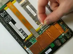
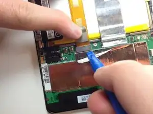
    • Peel protective foil cover back top of mother board to expose orange ribbon connection.

    • The ribbon connections should now be fully visible, with the plastic tabs exposed.

  6. vVkI6EGxv1JyTBHe
    vVkI6EGxv1JyTBHe
    oB2HWVBCL5NESv6X
    hQSUbJoWIvDTHlRG
    • Using the tweezers, peel back the silver protective foil on top of the orange ribbon connector.

    • Using the plastic opening tool, pry upward under the orange ribbon connector. It will pop right out of place.

  7. PtGFmOKWlncKdCK3
    PtGFmOKWlncKdCK3
    mEwQaOo34X5OKrwL
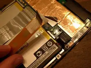
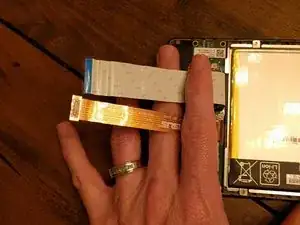
    • Now that the two main ribbons are disconnected, fold and hold them back with your fingers, or place the tweezers or a light object on the ribbons to keep them in place.

    How called is the left one ? I broke it and i will buy it but cant find it..

    Timo Dohmen -

  8. 5JPhFNGmbFcLRehZ
    • Use the #0 Phillips Screwdriver to remove the four silver 3 mm Philips #0 screws from around the battery housing.

    There are 6 screws on mine. One at the top and the other directly across from that on the other side of the battery at the bottom. These two screws are covered with a small adhesive sticker that says “seal". Those stickers need to be removed so the Phillips screwdriver can be inserted to remove them.

    dabair30 -

    Correcrion, there are 7. One more at the top left corner of the battery tray. The last 3 screws are slightly larger than the first 4.

    dabair30 -

    I found using a #00 Philips worked better for my removal.

    Todd -

    The WIFI only one is exactly as pictured. The LTE one has 3 more screws, two are the motherboard mounting screws (one with tamper sticker) and one at bottom on the other mainboard (also with tamper sticker). Other than that it is exactly the same.

    dick -

  9. FPOpL14uHChGauin
    • Remove the battery from your device by applying pressure at the base of the battery and lifting it out.

    If your replacement battery doesn’t have the metal battery tray included (like mine came) be aware you’ll have to CAREFULLY pry the old battery out of the metal tray. It has some pretty strong glue holding it in, but prying on it slowly and carefully should get it free without bending up the metal tray. There should be enough glue residue left in the tray to hold the new battery in, at least until you get the tablet back together.

    Tracy Nash -

    Thank you for the very helpful comment - I was facing the same issue!

    Jorge Gomes -

    You probably should add that the battery is held in the tray with some glue strips. It took a bit to carefully remove the battery from the tray without bending the tray too much. Also, the replacement battery I had was slightly smaller than the OEM battery. When putting back together make sure you place the battery in the tray so the battery is close enough to the battery connector and you can reconnect the battery without pulling on the connector wires.

    Todd -

    Having replaced the battery I find it doesn't charge. Which connector could be at fault please?

    mxclubman -

  10. J1W1BVfbCDl2SYPj
    • Use the tweezers to peel the seal sticker off of the center screw that is closest to the battery.

    • Make sure to store the seal in a place where it will not get dirty and will retain its stickiness.

    I couldn't get a grasp on the sticker enough to peel it off, so just punched through it with the screwdriver. I don't know the point of removing the sticker, since the warranty is voided anyway by either time or the mere act of disassembly.

    yuguoxiong -

    the stickers are probably put there for insulating purposes. i have found that discarding them has no bearing on nexus' operation.

    Leonard Gorsky -

  11. dJvdqTnrZKXUSgXR
    • Using the tweezers, or carefully with your fingers, disconnect the speaker from its motherboard connection by pulling directly sideways.

    • Do not pull upwards. Doing so may warp or damage the connector.

  12. UMeCSQcDXGPJNTXf

    The front panel assembly I got from iFixit didn't have this ribbon cable for power and volume, so I had to peel it off the old one. To remove it, work the spudger underneath and gently loosen it from the adhesive. There should be enough residual adhesive to stick it in place on the replacement panel assembly.

    yuguoxiong -

    your amendments are much appreciated. definitely helpful. THank YOU!

    Leonard Gorsky -

    I also had to remove the old ribbon cable here. I used a credit card to slide behind the adhesive.

    pattylanter -

    why in the world that part isnt included is beyond me. MUCH NEEDED COMMENT!!

    gocaps25 -

  13. tFNDvjOuPXIWru1H
    • Using the #0 Philips head screwdriver, remove the three black 2 mm screws holding the inner edge of the motherboard in place.

    • Using the #0 Philips head screwdriver, remove the five silver 3 mm screws holding the outer edge of the motherboard in place.

    There is also a ZIF connector on the BOTTOM of the motherboard that must first be released, before completely lifting the board out!

    Gary Lent -

    CORRECTION --- There is also a ZIF connector on the BOTTOM of the motherboard, connected to the camera. The camera must be pried loose before the motherboard can be lifted out. NO need to release ZIF.

    Gary Lent -

  14. yoImX1Q2A2KJJrT4
    yoImX1Q2A2KJJrT4
    nwgt4Cr1FJSMLWkp
    UStE3saXDhMQVTFM
    • Carefully lift the motherboard up from its edge and remove it from the tablet casing.

    • While the camera is connected directly to the motherboard from the bottom and might lift out of the tablet with the motherboard, it also might not. In this case, as shown, you'll need to use the tweezers to pry the camera out of its spot.

    • Removing the motherboard will reveal the top speaker that was being held down. If you are planning on replacing the top speaker, you may now simply pick it up out of the device.

    Careful when comparing to this picture. Actually, the camera which can be seen on the left oh the housing in this picture is connected to the board.

    Thomas Isele -

    Removing the camera is necessary, as it is impossible (with any tool I have, anyway) to reconnect the camera to the motherboard while it is still in the housing. However, doing so was quite a pain on my machine as it not only did not "lift out of the tablet with the motherboard", but it also was stuck in there so tightly I wondered if it might be glued. I needed to spend several minutes gently prying it out with pliers.

    pacmanmaster -

    Agreed!>>>> Camera is GLUED down, and must be pried prior to lifting out motherboard

    Gary Lent -

    I would add that it’s imperative to loosen the camera from its housing before attempting to remove the motherboard. The two are connected via another very short ribbon cable with zif connector. Trying to pull the motherboard out with the camera still stuck to the front could damage the cable/connector. In my mind it’s safer for both to come out together while still connected.

    Cool_Breeze -

    Also, see that conductive strip in the lower right corner of the first picture with the brownish tape on the metal backplane? Many replacements do not come with that. If you look on the back of the motherboard there is a copper strip that matches this conductive strip. It connects this copper strip on the motherboard to the metal backplane of the touch screen and helps the touchscreen work properly. It doesn’t peal off easily so work at it carefully.

    wa3pyi -

  15. aVXpT1gnmkOyBGpX
    aVXpT1gnmkOyBGpX
    WDMBwFGyOFf21BO6
    14UlCHtMWfDAV6L3
    • Flip the motherboard over.

    • Using your black nylon spudger, pop up the locking bar of the camera's ZIF connector.

    • Remove the rear facing camera from the motherboard.

Conclusion

To reassemble your device, follow these instructions in reverse order.

Sarah Westberg

Member since: 11/03/19

25075 Reputation

0 comments