Introduction

This repair guide was authored by the iFixit staff and hasn’t been endorsed by Google. Learn more about our repair guides here.

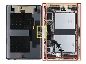
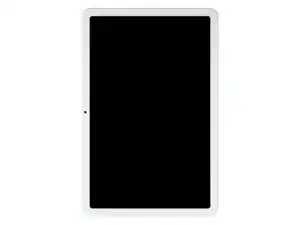
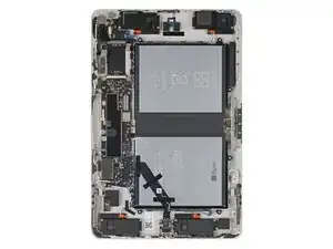
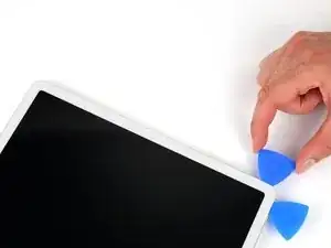
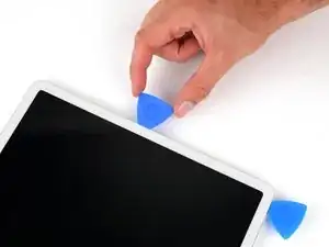
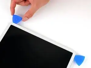
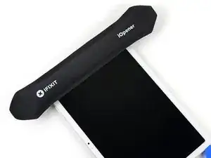
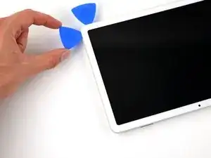
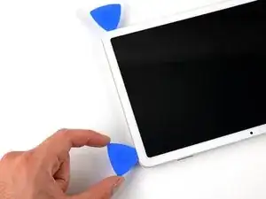
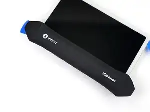
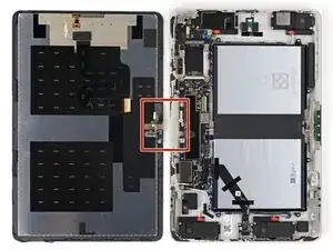
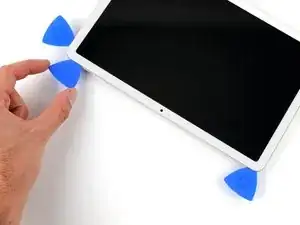
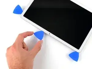
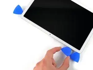
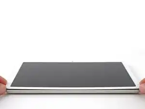
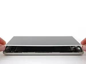
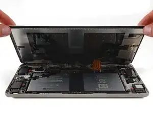
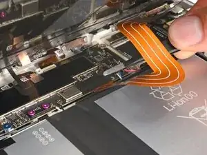
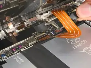
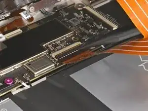
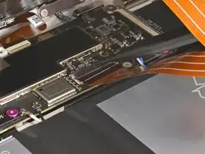
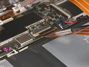
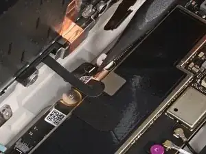
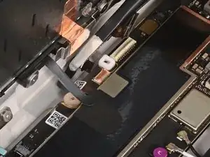
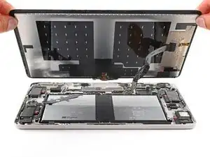
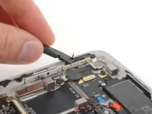
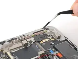
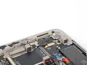
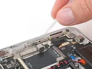
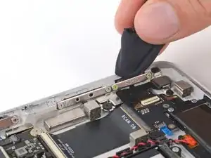
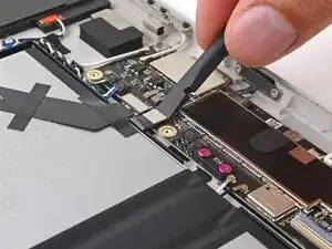
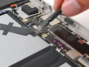
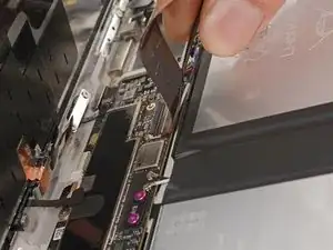
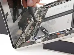
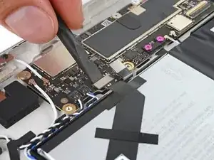
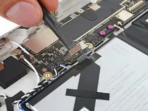
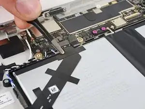
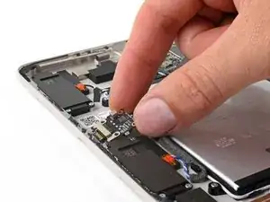
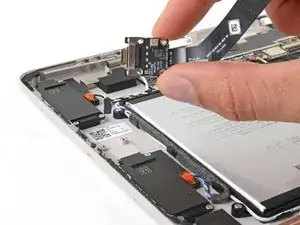
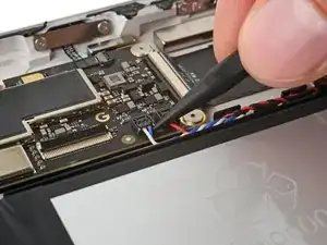
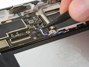
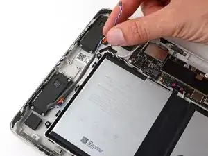
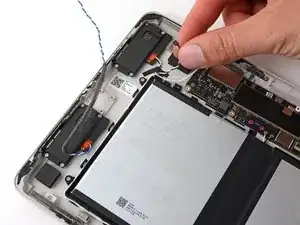
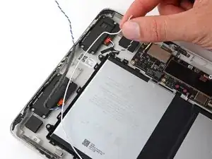
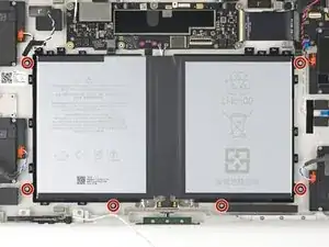
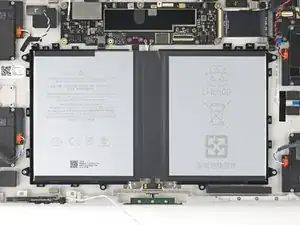
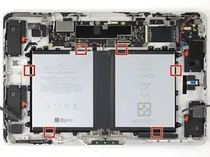
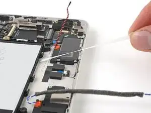
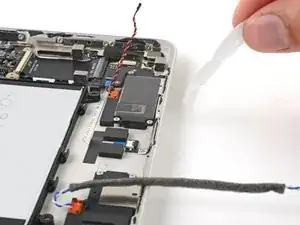
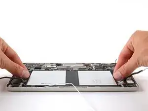
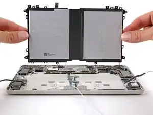
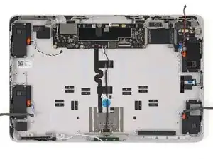
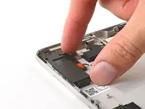
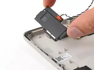
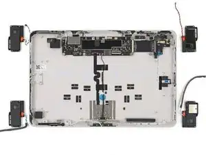
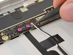
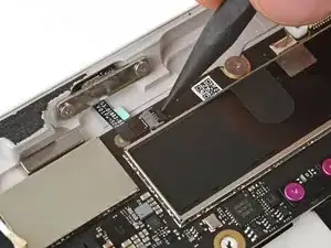
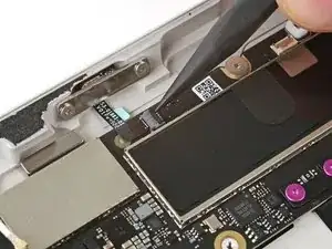
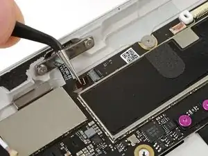
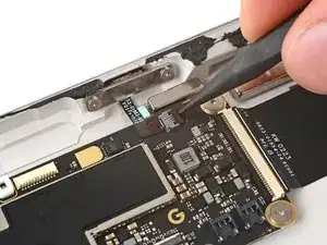
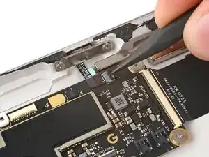
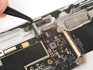
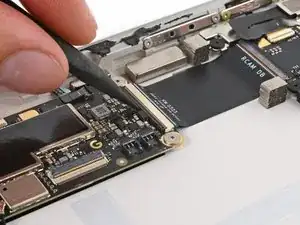
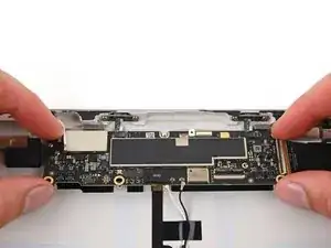
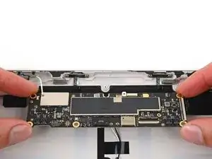
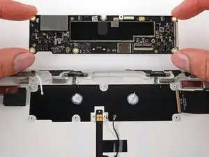
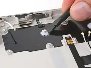
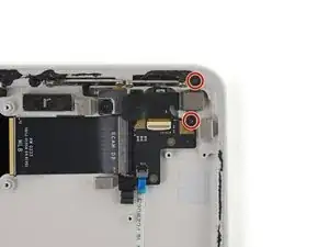
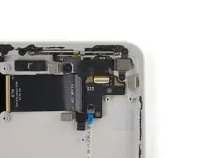
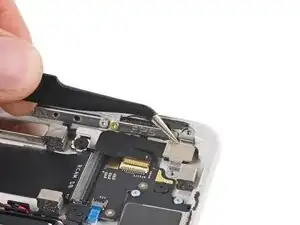
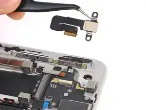
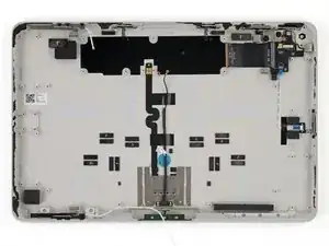
Use this guide to replace the enclosure in your Google Pixel Tablet.

This guide requires removing the battery and its tray. If your battery is swollen, make sure you have a replacement ready, and take appropriate precautions.

Note: You'll need thin, double-sided tape, such as Tesa 61395 Tape to secure the screen and complete this repair.

  1. ZvBI5QCsUmpKgBvU
    ZvBI5QCsUmpKgBvU
    JoIYBhRLlB4XCAU6
    • Allow your battery to fully drain before starting this repair. A charged battery may catch fire if damaged.

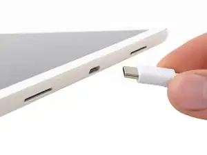
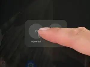
    • Unplug any cables from your tablet and fully power it down.

    • Hold the power and volume up buttons at the same time to bring up the power off menu.

    What if your screen is so badly damaged you can't see the power off menu (or anything else on the screen)?

    Lee Schneider -

  2. pOVReNPLi11Hb1Wo
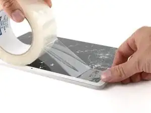
    • If your screen is badly cracked, lay overlapping strips of packing tape over the glass to protect yourself and make disassembly easier.

  3. BIvoCCnqDkHCh1Hm
    BIvoCCnqDkHCh1Hm
    moCmUknhLNsZoQob
    RDyZU3w5KaE3olj4
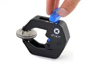
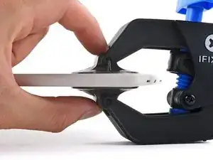
    • The next three steps demonstrate the Anti-Clamp, a tool we designed to make the opening procedure easier. If you aren't using the Anti-Clamp, skip down three steps for an alternate method.

    • For complete instructions on how to use the Anti-Clamp, check out this guide.

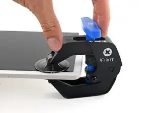
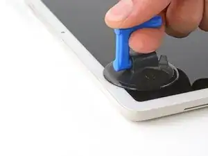
    • Pull the blue handle backward to unlock the Anti-Clamp's arms.

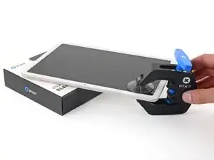
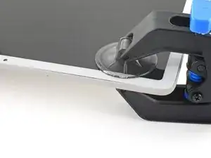
    • Slide the arms over the top left corner, with one suction cup on the back cover and one on the screen.

    • Place an object under your tablet so it rests level between the Anti-Clamp's arms.

    • Squeeze the cups together to create suction.

  4. CN1BYUslCjrrxLdd
    CN1BYUslCjrrxLdd
    sH3i2MTcIqPAINvv
    4GkhVRfJZyvRNYTP
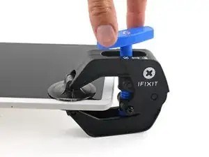
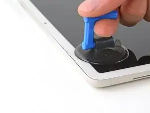
    • Pull the blue handle forward to lock the arms.

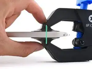
    • Turn the handle clockwise two full turns, or until the suction cups begin to stretch.

    • As the cups stretch, make sure they stay vertically aligned with each other. If they keep slipping, remove the Anti-Clamp and apply tape for the cups to stick to.

  5. LXEDOUfrMIUAWW6K
    LXEDOUfrMIUAWW6K
    AdHqULTdGaQOrR5F
    BAItQYOlKQupwKFG
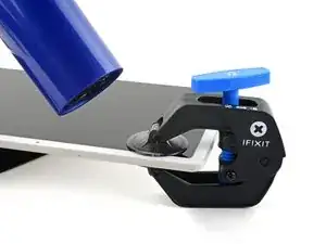
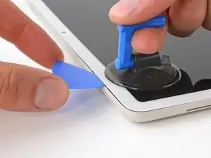
    • Use a hair dryer or heat gun to heat the top left corner of the screen until a gap forms between the glass and the frame.

    • Be careful not to overheat the tablet—the screen and battery are susceptible to heat damage.

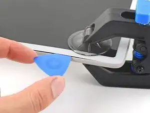
    • Insert an opening pick into the gap.

    • Remove the Anti-Clamp using the pull tabs on the suction cups.

  6. JwBGmoYbKvQxf2up
    • If you've already inserted an opening pick using the Anti-Clamp, skip down two steps.

    • Rotate your tablet so the front camera is closest to you.

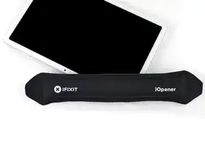
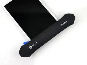
    • Apply a heated iOpener to the top left corner of the screen (now your bottom right, since the tablet is flipped around) for three minutes.

    • You can also use a hair dryer, heat gun, or hot plate, but be careful not to overheat the screen or battery—only heat the tablet so it's warm to the touch.

  7. TeYsPJvkvmpPVyeV
    TeYsPJvkvmpPVyeV
    hNmAZlrki6QFrxE6
    vIx5JLZCtpWGjUVN
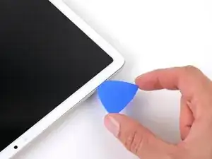
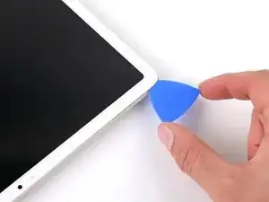
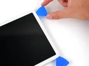
    • Apply a suction handle to the top left corner of the screen, as close to the top edge as possible.

    • Pull up on the suction handle with a strong, steady force until a gap forms between the glass and the frame.

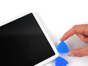
    • Insert the tip of an opening pick into the gap.

    • Remove the suction handle.

    This step is insanely hard. What the picture doesn't show is how to keep tablet from lifting off the table as you pull up. I've been at this step for an hour and the screen hasn't budged a half millimeter.

    Bryan Gillespie -

  8. oZjRYk5pOWYEbxeC
    oZjRYk5pOWYEbxeC
    W2WNqKoRGYUmheZA
    FRMqQNgQSSXTVXrI
    • The screen is secured with adhesive all around the perimeter. Note the following areas as you separate the adhesive:

    • The top, bottom, and left edges have the thickest adhesive.

    • The right edge has slightly thinner adhesive.

    • At the top, near the front camera, the adhesive is very thin and delicate cables connect the screen to the frame.

  9. TuceuE1Frb1tuUUt
    TuceuE1Frb1tuUUt
    2AcCPtL5HYCAMnD5
    • Don't insert your pick deeper than 7 mm, or about halfway between the tip of the pick and the iFixit logo.

    • Slide your opening pick to the top left corner of the tablet.

    • Leave this pick inserted to prevent the adhesive from resealing.

  10. FAHCueGFWILWR1ak
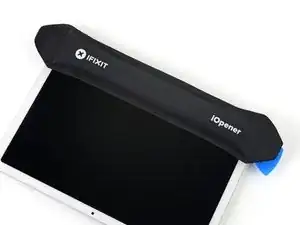
    • Apply a heated iOpener to the left edge of the screen for two minutes.

    • You can also use a hair dryer, heat gun, or hot plate, but be careful not to overheat the screen or battery.

  11. T5nQH1y5jhpOHuxL
    T5nQH1y5jhpOHuxL
    Bx1ETFrj3UpQQR5o
    • Don't insert your pick deeper than 7 mm, or about halfway between the tip of the pick and the iFixit logo.

    • Insert a second opening pick in the top left corner of the screen.

    • Slide your pick to the bottom left corner of the screen to separate the left edge adhesive.

    • Leave this pick inserted to prevent the adhesive from resealing.

  12. 2wL6rv24oHWUdqMb
    • Apply a heated iOpener to the bottom edge of the screen for two minutes.

    • You can also use a hair dryer, heat gun, or hot plate, but be careful not to overheat the screen or battery.

  13. RUHfVSOZtXrVTuIK
    RUHfVSOZtXrVTuIK
    deLWRY2tXECACtLP
    wjOEQVQZQuyi4rex
    • Don't insert your pick deeper than 7 mm, or about halfway between the tip of the pick and the iFixit logo.

    • Insert a third opening pick in the bottom left corner.

    • Slide your pick to the bottom right corner of the screen to separate the bottom edge adhesive.

    • If your pick becomes stuck, repeatedly twist it as you slide to help separate the adhesive.

    • Leave this pick inserted to prevent the adhesive from resealing.

    If your screen has cracks that extend to the edge, this step is insanely hard as well. The pick will not be able to slide cleanly under the crack boundaries. 10/10 difficulty repair for cracked screens.

    Bryan Gillespie -

  14. NyDgfRffxTOrANG4
    • Apply a heated iOpener to the right edge of the screen for two minutes.

    • You can also use a hair dryer, heat gun, or hot plate, but be careful not to overheat the screen or battery.

  15. HCvqEFp4Unb6HKuj
    HCvqEFp4Unb6HKuj
    bU6TxR3HSRilUFxJ
    • Don't insert your pick deeper than 5 mm along the right edge.

    • For a visual reference, you can measure 5 mm from the tip and mark your pick with a permanent marker.

    • Insert a fourth opening pick in the bottom right corner.

    • Slide your pick to the top right corner to separate the right edge adhesive.

    • Leave this pick inserted to prevent the adhesive from resealing.

  16. wrHRBJVVRuFUBbRF
    • Apply a heated iOpener to the top edge of the screen for two minutes.

    • You can also use a hair dryer, heat gun, or hot plate, but be careful not to overheat the screen or battery.

  17. sIQ51pAGYsLLSNcY
    • The front camera and sensor are along the middle of the top edge. Be very careful not to insert your opening pick deeper than 3 mm (1/8 in) here.

    • For a visual reference, you can measure 3 mm from the tip and mark your pick with a permanent marker.

    • To mark where to avoid slicing too deep, it can be helpful to put a 6.3 cm (2.5 in) long strip of masking tape on the top edge, centered over the front camera.

  18. mqrLUQT3eOAfsgEH
    mqrLUQT3eOAfsgEH
    pKNNLStmcnytxnKl
    m1F3pKMGZtrQkGDp
    • Insert a fifth opening pick in the top right corner of the screen.

    • Slide your pick toward the front camera. Stop when your pick is 3 cm (1.25 in) from the front camera.

    • Pull your pick out to a depth of 3 mm (1/8 inch) and slide it past the front camera.

    • When your pick is 3 cm past the front camera, insert it up to 6 mm deep, or about halfway between the tip and the iFixit logo, and slide it to the first pick you left in the top left corner.

  19. IphSkuTLeXJxroqT
    IphSkuTLeXJxroqT
    isH6K231EF1BZAFP
    5cKM4kQMFC1ceWZ5
    • Don't tilt the screen open beyond 90 degrees. The front camera and sensor cables are very short and may tear.

    • Grab and lift the bottom corners of the screen.

    • If the screen feels stuck, check around the perimeter for any missed sections of adhesive and slice them with an opening pick.

    • Tilt the screen open just enough to access the cables connecting the screen to the frame.

    • During reassembly, remove the adhesive liners from the perimeter of the screen before firmly pressing it into place in the frame.

  20. d4aBYMO5GZLmGtX6
    d4aBYMO5GZLmGtX6
    wN4QNaCDiFyPKBrN
    6PQEHpgGDSb3Jpe4
    • For the next three steps, hold the screen tilted open with one hand while you work with your other hand.

    • If you have difficulty holding up the screen, place the tablet's dock on the frame to prop up the screen or ask someone to hold it up while you work.

    • Use tweezers to peel and remove the black tape off of the screen cable connector.

    • During reassembly:

    • Install new tape if the old piece is damaged and you have a replacement from your repair kit.

    • Now is a good time to test your tablet before sealing it up. Power it on and check that it works. Power it back down before you continue reassembly.

  21. MDpgyaa5dN5DygE3
    MDpgyaa5dN5DygE3
    YEqcgm1Mph1ljlsI
    M5BZCcHFFqJ4gs1L
    • Use the point of a spudger or a clean fingernail to flip up the small locking flap on the inside edge (same side as the cable) of the screen cable ZIF connector.

    • Use tweezers or your fingers to pull the screen cable straight out of its socket.

  22. IGYIWqvn2EDVYFuJ
    IGYIWqvn2EDVYFuJ
    lT5EIpaN4tRsmurR
    EFkQn3TonrB6tJrY
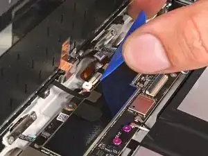
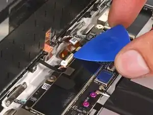
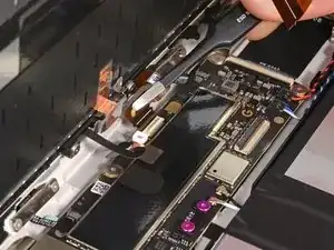
    • Use an opening pick to flip up the small locking flap on the outside edge (opposite the cable) of the front camera ZIF connector.

    • Use tweezers to pull the cable straight out of its socket.

    • During reassembly, be careful not to tear this cable, since it doesn't have much room to bend. Guide the connector into its socket with tweezers and lock the ZIF connector flap at the same time.

  23. JoZA53ayy5BpgIvr
    JoZA53ayy5BpgIvr
    ZTUOFEPTE2hflegw
    16uJMFNaLDMpP262
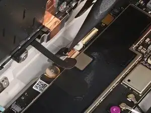
    • Use the point of your spudger or a clean fingernail to flip up the small locking flap on the inside edge of the front sensor connector.

    • Use tweezers to pull the cable straight out of its socket.

  24. X31PFHjDKxnhcLJG
    • Remove the screen.

  25. r4cx4KkenXRwuul3
    r4cx4KkenXRwuul3
    oAQaxvI1bwMAvS1Q
    hPpRfot3Sc3hxrWb
    • Follow the next two steps to clean your frame and prepare it for reassembly.

    • Use the flat end of your spudger or a clean fingernail to scrape up an edge of the leftover frame adhesive until you can grip it.

    • Use tweezers or your fingers to peel off large pieces of adhesive from the frame.

    • Repeat this process around the entire perimeter of the frame until there are no large pieces are left.

    • If you're reusing your screen, remove the old adhesive from it as well as the frame.

  26. XwqlXMgDWgMMNRlK
    XwqlXMgDWgMMNRlK
    JWOtqkQuYGerbVmW
    QYshm4DLANYKH2oX
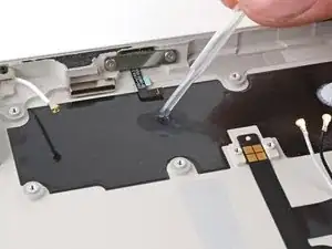
    • Fill a pipette or syringe with highly-concentrated isopropyl alcohol (over 90%) and apply a few drops to the edge of the frame.

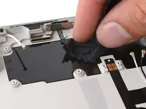
    • Wrap a microfiber or lint free cloth around the flat end of your spudger and scrub the frame until it's clean. Use more isopropyl alcohol as you go.

    • If you're reusing your screen, clean its perimeter as well as the frame.

  27. kPn3rOQvOvVCYiYM
    kPn3rOQvOvVCYiYM
    xvINyMuvPmcGBRDL
    TA3u6JTMcieIvbb2
    • While the Pixel Tablet uses Torx Plus screws, standard Torx bits work in a pinch. Make sure to apply constant, downward force to prevent stripping.

    • Use a Torx Plus 3IP driver to remove the two 2.6 mm screws securing the battery, USB-C, and speakers connectors cover.

    • If you're using standard Torx bits, a T3 Torx will work best for these screws. If it feels too loose, you may need a T4 Torx bit.

    • Remove the cover.

  28. FML6OQwWfnb2NYbt
    FML6OQwWfnb2NYbt
    SF4rfObFmrsQUORs
    • Use the flat end of your spudger to pry up and disconnect the battery press connector.

    • To reconnect a press connector, align it over its socket and gently press down on one side until it clicks into place, then press down on the other side.

    Why we have to disconnect battery connector here if we only want to replace screen? for safety? or other concern? thanks.

    Shiryu Lee -

    Yes, you're right about safety! The wide screen cable is very delicate and prone to shorting if it's inserted wrong. The danger is reflected in the reassembly step farther down in the guide. Essentially, you risk shorting the connector and creating a fire hazard if power runs through an improperly connected screen cable.

    Clay Eickemeyer -

  29. bTCLhH1lnP6wJeWY
    bTCLhH1lnP6wJeWY
    EWEbqhEpnFrEtEeE
    vmKbmhLGQQSj2KXQ
    • Connecting the screen cable with the battery connected risks shorting the connector and poses a fire hazard.

    • Follow this step during reassembly to safely reconnect the screen and battery.

    • Prop up the bottom edge of the tablet on a box or similar object. Tilt the screen open and lean it against something so that it's angled up to 90 degrees.

    • Reconnect the small front sensor cable ZIF connector.

    • Reconnect the large screen cable ZIF connector.

    • Reconnect the battery press connector.

    • Use your Torx Plus 3IP driver to install the two 2.6 mm screws and fasten the connector cover.

    • Continue reassembly with these cables connected.

  30. Ki11QjCvurIaQh2J
    Ki11QjCvurIaQh2J
    X5USjINa3Y1koYeG
    • Use the flat end of your spudger to pry up and disconnect the USB-C port press connector.

  31. sYj3G23AP3TXMAFb
    sYj3G23AP3TXMAFb
    f6SxLvuQpPrVTpiH
    wdTgnvkq4xX4Z3BA
    • Be careful not to damage the battery with your tool during this step.

    • Use blunt nose tweezers or your fingers to peel up and remove the three strips of tape securing the USB-C port cable to the battery.

    • During reassembly, reuse these strips of tape if they're in good condition. If not, cut and apply a few thin strips of electrical tape to re-secure the cable to the battery.

  32. 22jtIdKUHV2SOWPD
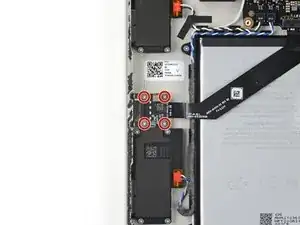
    • Use your Torx Plus 3IP driver to remove the four 3.2 mm screws securing the USB-C port.

  33. HkxDjuDGJfjbiblw
    HkxDjuDGJfjbiblw
    uZifUHbR3rKSFSvU
    MsrBcMOhVFL2nbos
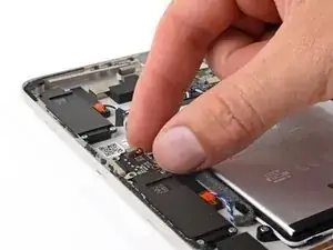
    • Pull the USB-C port out of its recess in the frame and remove it.

  34. 6qXZVGTSMmTWDg2Y
    6qXZVGTSMmTWDg2Y
    2TMwa4sRjoJnc2cs
    uT6JD3WkZFukIcNx
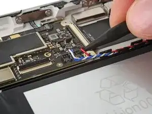
    • Use the point of your spudger to lift up and disconnect the blue and white speaker cable connector from the right side of the logic board.

    • Pry straight up on the neck of the cables, as close to the head of the connector as possible.

    • Disconnect the red and black speaker cable connector.

  35. EXLPmeBaQB2QDcSi
    EXLPmeBaQB2QDcSi
    YVNqdWADEScPSiMM
    H5Wo1ZmShS22XWa5
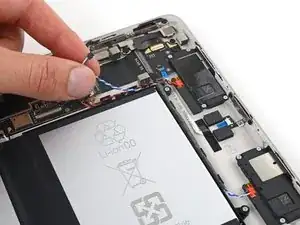
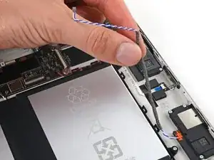
    • Pull the blue and white speaker cables out from their clips along the top and right edges of the battery tray.

    • Pull the red and black speaker cables out from their clips along the top of the battery tray.

  36. pCbZHqCE4oY64CJG
    pCbZHqCE4oY64CJG
    tXnmUEgTUOHGAZ2V
    R6e2DjR2NF2VXoAf
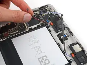
    • Use the point of your spudger to pry up and disconnect the blue and white speaker cable connector from the left side of the logic board.

    • Pry straight up on the neck of the cables, as close to the head of the connector as possible.

    • Disconnect the black and white speaker cable connector.

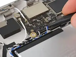
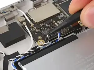
    • Disconnect the left antenna connector from the logic board by prying the metal neck of the cable straight up.

  37. UKOHmbWpkvUUjLmu
    UKOHmbWpkvUUjLmu
    xVx2lZKKlnoPoOpD
    tJhEpVyUYl1LGEvO
    • Pull the speaker cables and antenna cable out from the clips securing them along the battery tray.

  38. NUnZouxoNB1OXO1K
    NUnZouxoNB1OXO1K
    4IGopjXxHpBL13lR
    • Use a Torx Plus 2IP driver to remove the six 2.8 mm screws securing the battery tray.

  39. 1TxWO1iTwIgBixIg
    1TxWO1iTwIgBixIg
    NBfeKhMMMhfIHOFJ
    gI6GetDBTtSBCSHS
    • Six strips of stretch-release adhesive run underneath the battery tray, securing it to the frame.

    • Use tweezers to peel back the six white pull-tabs on the battery tray's stretch-release adhesive strips.

    • Don't try to remove the battery cells from the black tray.

  40. c5cUo3oBTn3DESO6
    c5cUo3oBTn3DESO6
    PtDDZjcAR4yWVWyL
    XjGGcICVC3ogLHLd
    • Grab an adhesive strip's pull tab and slowly pull it out from underneath the battery tray.

    • Pull the adhesive strip at as low of an angle as you can. Try to avoid dragging it across components inside the frame.

    • Pull the adhesive strip until it's freed from under the battery tray. Give the strip plenty of time to stretch.

    • Repeat for all six adhesive strips.

    • Use your spudger to depress the piece of foam near the lower right strip as you pull.

    • If any strips broke off and you can't retrieve them:

    • Use a pipette or syringe to dispense a few drops of highly-concentrated isopropyl alcohol (over 90%) under the sections of the battery tray where the strips broke. Tilt the tablet to let the isopropyl alcohol flow underneath.

    • Wait two minutes, then use a spudger to pry up the battery tray.

  41. CYMdIiyVhP5bjtMk
    CYMdIiyVhP5bjtMk
    A4BNYu6bcASNhhoP
    • Remove the battery, still attached to its tray, from the frame.

    • Don't reuse a deformed or damaged battery, as doing so is a safety hazard.

    • During reassembly, if you're installing a new battery, remove the liners from the six adhesive strips on the underside of the battery tray and press it firmly into place. Use the six screw posts to help align the tray to the frame.

  42. dcjim44NNY3lSoas
    dcjim44NNY3lSoas
    ubPIhAHAKxdrQrnH
    HEIFLaX64bLrWP3I
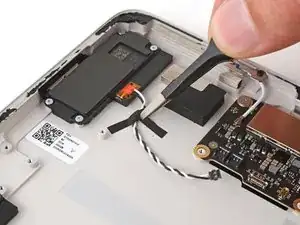
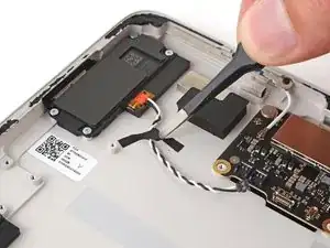
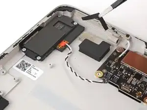
    • Use tweezers or your fingers to peel up and remove the tape securing the black and white speaker cable to the enclosure.

    • During reassembly, reuse this tape if it's in good condition. If not, cut and apply a thin strip of electrical tape to re-secure the cable to the enclosure.

  43. yMPGQGIDViNvVWHa
    yMPGQGIDViNvVWHa
    DcfCauwKVMjfCeqx
    • Use a Torx Plus 2IP driver to remove the sixteen 2.7 mm screws securing the four speakers.

    • If you're using standard Torx bits, a T3 Torx will work best for these screws. If it feels tight, you may need a T2 Torx bit.

  44. PyFcwmQJoGHkRkyK
    PyFcwmQJoGHkRkyK
    VFRAkqABTdWeeEoF
    22qXTlcLHAqoiRtZ
    • Remove the speakers.

  45. BMaTAbpnUxXqpBvZ
    BMaTAbpnUxXqpBvZ
    DAUGmLesxoUnNWip
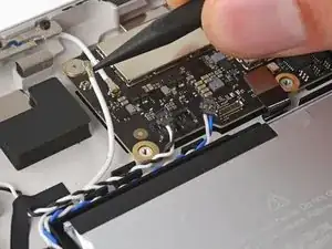
    • Use your spudger to disconnect the left antenna connector by prying the metal neck of the cable straight up.

  46. uaD2SQcL2W6DXFlW
    uaD2SQcL2W6DXFlW
    4scHEOfXOVrANfNT
    yXKXg6h2M3sNUXDi
    • Disconnect the lower two antenna cables.

  47. 3WU31fGgGUZDyrmn
    3WU31fGgGUZDyrmn
    kYSVbhgaxdLtEZiJ
    aGR4OMuCL1EBdYaR
    • Flip up the small locking flap on the outside edge of the left ZIF connector and pull the cable straight out of its socket.

  48. aiQUraP6QYrIS5ef
    aiQUraP6QYrIS5ef
    R3yQdJY5b15qFeTu
    YAnmKkflGQ5512fL
    • Use the point of your spudger or a clean fingernail to flip up the small locking flap on the outside edge of the right ZIF connector.

    • Use tweezers to pull the cable straight out of its socket.

  49. xMWfiNOorg6KDeyH
    xMWfiNOorg6KDeyH
    IuHVVZ4vINTI1P2G
    DtQblXmPpfV3NCRX
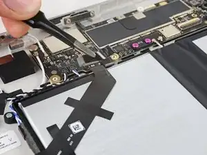
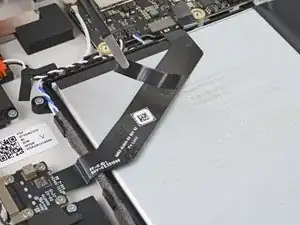
    • Use the point of your spudger or a clean fingernail to flip up the wide locking flap on the outside edge of the interconnect cable ZIF connector.

    • Use blunt nose tweezers to pull the cable straight out of its socket.

    • The cable is adhered to the enclosure. If you have trouble disconnecting it, peel the cable from the frame near the connector.

  50. wFPehqdqjO5I66Ym
    wFPehqdqjO5I66Ym
    YQMOt3wPC1RvlE15
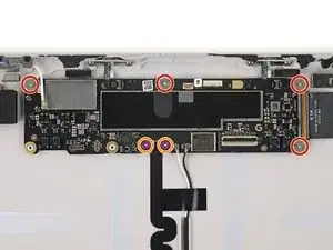
    • Use your Torx Plus 3IP driver to remove the six screws securing the logic board:

    • Four 2.2 mm screws

    • Two 3.2 mm screws

  51. AwFkeVTqfA1wxwwQ
    AwFkeVTqfA1wxwwQ
    IrQUVXMy63GDsxXT
    53GL1KHGSrjTMIG6
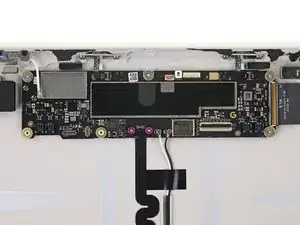
    • Tilt the bottom of the logic board up and away from the frame to separate the thermal paste.

    • Slide the logic board toward the bottom of the tablet to clear the ZIF cables along the top of the frame.

    • Remove the logic board.

    • Be careful not to lose the black washer on the bottom edge of the logic board. If it falls off, make sure to put it back before installing the logic board screws.

    • During reassembly, hold the ZIF cables up as you slide the logic board into place.

  52. Mr3emTG5TmmysYG5
    Mr3emTG5TmmysYG5
    I5LsLerrKShUDPEM
    HAIPfvQ5oU6HHZJL
    • If you're reusing your frame, follow this step to clean the thermal paste from it. If not, skip down one step.

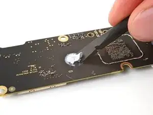
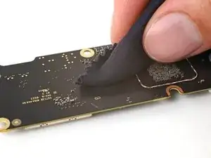
    • Use the flat end of your spudger to gently scrape away large pieces of thermal paste.

    • If you're reusing your enclosure, be careful not to tear the graphite film.

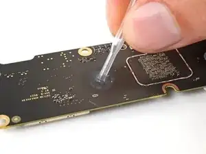
    • Use a pipette or syringe to apply a couple drops of highly-concentrated isopropyl alcohol (over 90%) to the thermal paste residue.

    • Use a microfiber or lint-free cloth to wipe the frame clean.

  53. rwP1YLVJCn4jGBS6
    rwP1YLVJCn4jGBS6
    iZbOyCbtQ2LxmcC4
    jqS6yB4DmB15BQoY
    • Gently scrape away large pieces of thermal paste from the logic board.

    • Apply a couple drops of isopropyl alcohol to the thermal paste residue.

    • Wipe the logic board clean.

    • During reassembly, follow this guide to apply new thermal paste to the logic board.

  54. 3vHIQqQCjLYTLAjZ
    3vHIQqQCjLYTLAjZ
    uvLBTA4EuReYxdxE
    bpATNNOeLhiEGdGn
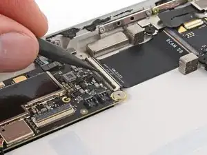
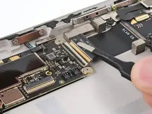
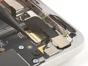
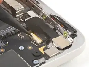
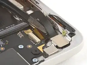
    • Use the point of your spudger or a clean fingernail to flip up the small locking flap on the outside edge of the rear camera ZIF connector.

    • Use blunt nose tweezers to pull the cable straight out of its socket.

  55. VWUsclSPklvuwmVr
    VWUsclSPklvuwmVr
    P46AuioJh5KfYWtK
    • Use your Torx Plus 3IP driver to remove the two 2.2 mm screws securing the rear camera bracket.

  56. 2p2b32XhfHBKJPH2
    2p2b32XhfHBKJPH2
    eBKDKgxShQF53xKD
    • Remove the rear camera.

  57. IUjTfkdhRegVXUHS
    • Only the frame remains.

Conclusion

To reassemble your device, follow these instructions in reverse order.

Take your e-waste to an R2 or e-Stewards certified recycler.

Repair didn’t go as planned? Try some basic troubleshooting, or ask our Answers community for help.
Clay Eickemeyer

Member since: 19/09/22

72988 Reputation

0 comments