Introduction

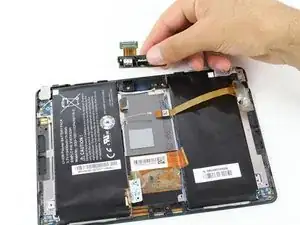
Both front and back cameras are connected as a single assembly and must be replaced together.

  1. mb4SlXf6oLBjnsfP
    mb4SlXf6oLBjnsfP
    OxUr2IQaGE1OjSSo
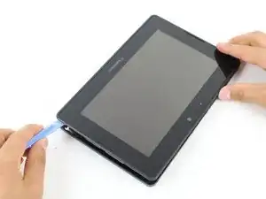
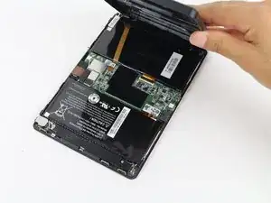
    • Use a plastic opening tool to pry the back panel off by inserting it in between the front and back panel.

    • There are clips that need to be released on all four sides of the device.

    • When replacing the back cover insert the bottom side first ( usb and hdmi ports stick out about 2mm ) inserting them into the covers openings will allow for easier reassembly

  2. 5wLehSIMYiWYnmlh
    5wLehSIMYiWYnmlh
    iWkFKSpuaDbVfEBN
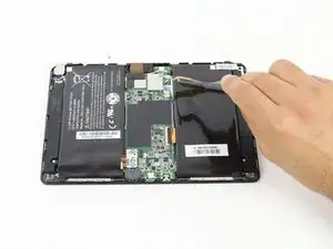
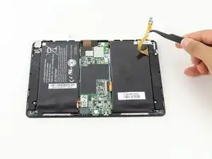
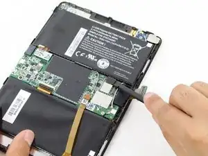
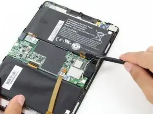
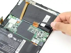
    • Remove the battery connector using either your fingers or a pair of tweezers.

  3. lsMNPxvW6fDD2jPv
    lsMNPxvW6fDD2jPv
    HTaKJaYbTSC3O3nI
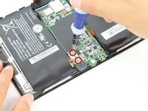
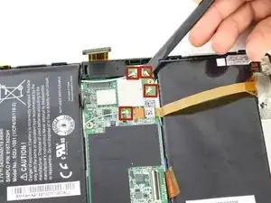
    • Unscrew two 1.17x2.9mm Phillips screws from the white connector port.

    • Lift the battery connector away from the motherboard using a spudger.

  4. PbVO1MTFuxQGkwN2
    PbVO1MTFuxQGkwN2
    oSQiNKJgRfyuGJwS
  5. falCJQXHucsXVXAD
    falCJQXHucsXVXAD
    UiGWBuYUIHHYA3au
  6. fWJNxLWp2aOAGqcs
    fWJNxLWp2aOAGqcs
    jmJv166pVxNsu3kW
    vEZWDTRMsHxnI662
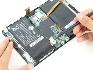
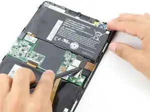
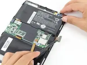
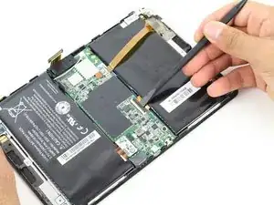
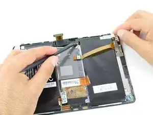
    • Remove the clipped ZIF data connector coming from underneath the motherboard.

    • Lift up the black plastic clip with a spudger.

    • Pull the connector out gently using tweezers.

    • Be careful to ensure that the black plastic clip has been lifted away from the connector ribbon before pulling on the connector. The clip should be loose and easy to wiggle. Removing the connector before it is unclipped can cause damage.

  7. tfE2UAnO2QwALRsU
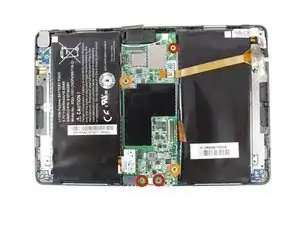
    • Remove the following five screws from the motherboard.

    • Three 1.5x2.5mm Phillips screws

    • Two 1.55x2.38mm Phillips screws

  8. UJgUkGWeelNR6Htm
  9. cJKgaCfEbJpTADGr
    cJKgaCfEbJpTADGr
    2yMPYg5yTPpJSljj
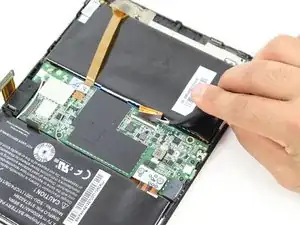
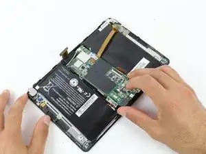
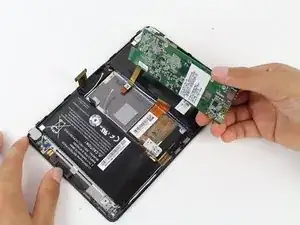
    • Gently lift the motherboard away from the device. If there is any resistance, check the previous steps to ensure that all connections have been removed.

  10. KnNFIUcwjpLfJsXg
  11. QwADDA4mERx2QWtE
    QwADDA4mERx2QWtE
    5Q2VEgvwSJqOYTLE
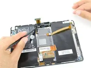
    • Pry the camera assembly away from the device, lifting the left side with a spudger.

    • There is a small hook on the right side of the assembly holding it in place. When removing the assembly, be sure to lift it from the left side in order to slide it out from under this hook.

  12. 1NBm1VtSUoHxYNhy
    1NBm1VtSUoHxYNhy
    BKVDM2XBlRCIc4J5
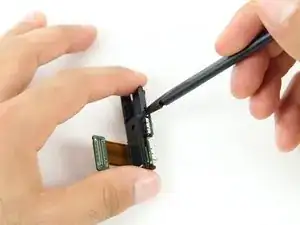
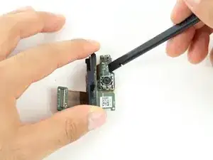
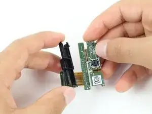
    • Insert spudger between the plastic frame and circuit board.

    • Gently pry the plastic frame away from the rest of the camera assembly.

Conclusion

To reassemble your device, follow these instructions in reverse order.
Nathan

Member since: 12/10/14

673 Reputation

0 comments