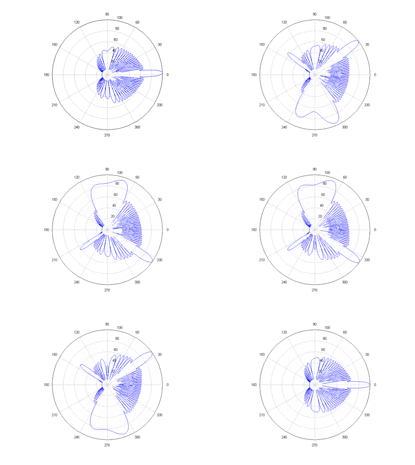
For discrete aperture antennas (such as phased arrays) in which the element spacing is greater than a half wavelength, a spatial aliasing effect allows plane waves incident to the array from visible angles other than the desired direction to be coherently added, causing grating lobes. Grating lobes are undesirable and identical to the main lobe. The perceived difference seen in the grating lobes is because of the radiation pattern of non-isotropic antenna elements, which effects main and grating lobes differently. For isotropic antenna elements, the main and grating lobes are identical.
Definition
In antenna or transducer arrays, a grating lobe is defined as "a lobe other than the main lobe, produced by an array antenna when the inter-element spacing is sufficiently large to permit the in-phase addition of radiated fields in more than one direction."[1]
Derivation

To illustrate the concept of grating lobes, we will use a simple uniform linear array. The beam pattern (or array factor) of any array can be defined as the dot product of the steering vector and the array manifold vector. For a uniform linear array, the manifold vector is , where is the phase difference between adjacent elements created by an impinging plane wave from an arbitrary direction, is the element number, and is the total number of elements. The term merely centers the point of reference for phase to the physical center of the array. From simple geometry, can be shown to be , where is defined as the plane wave incident angle where is a plane wave incident orthogonal to the array (from boresight).[2]
For a uniformly weighted (un-tapered) uniform linear array, the steering vector is of similar form to the manifold vector, but is "steered" to a target phase, , that may differ from the actual phase, of the impinging signal. The resulting normalized array factor is a function of the phase difference, .[3]
The array factor is therefore periodic and maximized whenever the numerator and denominator both equal zero, by L'Hôpital's rule. Thus, a maximum of unity is obtained for all integers , where . Returning to our definition of , we wish to be able to steer the array electronically over the entire visible region, which extends from to , without incurring a grating lobe. This requires that the grating lobes be separated by at least . From the definition of , we see that maxima will occur whenever . The first grating lobe will occur at . For a beam steered to , we require the grating lobe to be no closer than . Thus .
Relationship to sampling theorem
Alternatively, one can think of a uniform linear array (ULA) as spatial sampling of a signal in the same sense as time sampling of a signal. Grating lobes are identical to aliasing that occurs in time series analysis for an under-sampled signal.[4] Per Shannon's sampling theorem, the sampling rate must be at least twice the highest frequency of the desired signal in order to preclude spectral aliasing. Because the beam pattern (or array factor) of a linear array is the Fourier transform of the element pattern,[5] the sampling theorem directly applies, but in the spatial instead of spectral domain. The discrete-time Fourier transform (DTFT) of a sampled signal is always periodic, producing "copies" of the spectrum at intervals of the sampling frequency. In the spatial domain, these copies are the grating lobes. The analog of radian frequency in the time domain is wavenumber, radians per meter, in the spatial domain. Therefore the spatial sampling rate, in samples per meter, must be . The sampling interval, which is the inverse of the sampling rate, in meters per sample, must be .
References
- ↑ IEEE Std 145-2013, "IEEE Standard for Definitions of Terms for Antennas"
- ↑ Van Trees, H.L. Optimum Array Processing. pp. 42–53.
- ↑ Van Trees, H.L. Optimum Array Processing. p. 54.
- ↑ Van Trees, H.L. Optimum Array Processing. p. 51.
- ↑ Mailloux, R.J. (2005). Phased Array Antenna Handbook. Norwood, MA: Artech House. pp. 109–111.