Introduction

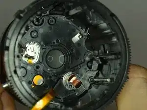
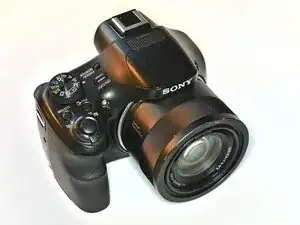
This will be an complete teardown of the camera. The camera, that was torn down had problems with the moving lens.

  1. LmK4dMsPiedkLDuC
    • 20.4 MP CMOS Sensor

    • 50x Optical Zoom

    • GPS, NFC and WiFi

  2. JdjmlmPyc5nZu4cY
    JdjmlmPyc5nZu4cY
    ZaSbMnRUgUvMIpos
    y5f2pKbeqcPvNSvi
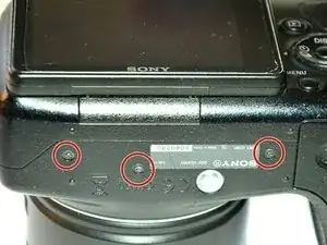
    • Remove the eight screws.

    Size 0 IFIXIT screwdriver bit.

    Bummers -

    These screws are black, fine thread 4.3mm long.

    Bummers -

  3. F1sVxVwnwBBgYLQD
    F1sVxVwnwBBgYLQD
    GTceBbJBLHU2Cn3h
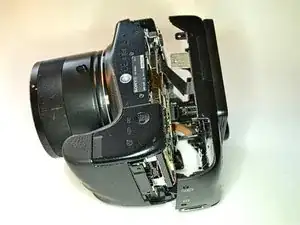
    • Begin with the bottom and pull the case apart.

    • Be careful with the ribbon cable of the display.

  4. BVYNCNtOdP5CEvEe
    BVYNCNtOdP5CEvEe
    5SYMfJk2mqCOGBbZ
    nSrYr2WQ6CTEJZHl
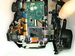
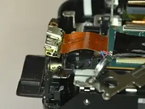
    • Free up the connector under the black tape.

    • Disconnect the ribbon cable.

    • You need to pull up the brown edge of the connector to open it. (Here shown with another connector of the next step.)

    • This cable is used to connect the display as well as the button on the rear site to the mainboard.

  5. UJtY6QoIpRJGhSAi
    UJtY6QoIpRJGhSAi
    Mr2YNQ2UEkYGKCNf
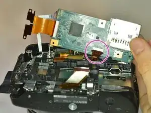
    • Disconnect all seven remaining ribbon cables.

    • Disconnect these with the technique from the last step.

    • Simply pull these out of the connector. There are small edge at the cable to easily pull them out.

  6. dDrUYEu5QPdvWqX6
    dDrUYEu5QPdvWqX6
    CYfMZRRrKIOPSPQG
    • Unscrew both screws

    • Take out the bracket. You can then remove the bracket from the speaker.

    • Be careful with the cable between the speaker and the motherboard.

    • The speaker bracket is also the mount for the camera strap.

    Both screws, “self tapper” style, black, 5.3mm long.

    Bummers -

  7. tid6w6fKf3Y3NnWh
    tid6w6fKf3Y3NnWh
    qG3EMawKkycllnkR
    ZipdyZBrtPSvSZOT
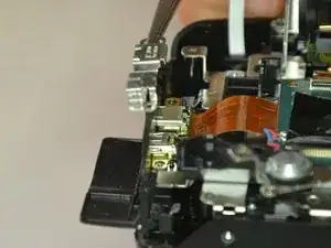
    • Unscrew all three screw that are holding the bracket down.

    • Lift up the bracket and then the connectors.

    These three screws are silver color (stainless steel?)

    Bummers -

    All 3 screws 3.8mm long.

    Bummers -

  8. AJ5XYqPCoMajs6OJ
    AJ5XYqPCoMajs6OJ
    e6ONRmhuF4Vqc1VX
    • Unscrew the three screws.

    • Be careful with the small cable to the NFC (and WiFi?) antenna which is glued to the battery case.

    • Turn the mainboard around and disconnect the last ribbon cable.

    3 x screws, silver, 3.8mm long.

    Bummers -

  9. wdbEYLONyIdTixPS
    • Unscrew the four screws.

    • Note that the two bottom screws are shorter than the others.

    • The viewfinder sits inside the bracket of the flash socket. On right beside the electronic viewfinder (aka display with lens), there is the proximity sensor which is used to switch between the display and the viewfinder.

    The 2x top longer screws are 5.3mm long, black, “self-tapper” style thread.

    The 2x bottom screws are only 2.4mm long, also black but fine thread.

    Bummers -

  10. RJo4hDXc4rkDKNSP
    RJo4hDXc4rkDKNSP
    RUFGrqnSf4MRoLHj
    4hdSVMSkdwoBFrKQ
    • Frontglass holder

    • Frontglass, you may want to clean it, if you have disassembled it

    • Lens with spring. This is used to give you a sharp view into the viewfinder. The small nib is pushed in different positions by the small dial on the case to adjust the focus for your eyes

    • Monitor, a very small monitor. Looks much like the image sensor.

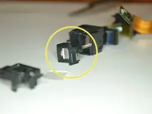
    • Proximity sensor for detecting your eye and therefore switching to the viewfinder.

    • PCB with 2 unidentified ICs (659L and 3232 615)

    • Backcover

  11. dAfA3hklL4yguwaI
    dAfA3hklL4yguwaI
    TTRIjblQbAUEFTec
    bsoHnavfn4tNVCwL
    • Disconnect the ribbon cable to the GPS module at the top.

    • Unscrew the last two screws of the baseplate. Then pull the baseplate to back.

    • Be careful with the GPS module when pulling out the baseplate.

    These 2 screws are 5.3mm long, black, with “self-tapper” style threads.

    Bummers -

  12. sghrvfHx41AxJNoC
    sghrvfHx41AxJNoC
    rSRKpOIkylJtUDFZ
    • Unscrew the battery case and pull it out.

    • Make sure you have DISCHARGED the flash capacitor before. Now you could touch it and may get a electrical shock. It is rated for 315 V and 134µF.

    • Be careful again with the cable between the mainboard and the antenna.

    • Disconnect the ribbon cable, unscrew the flash PCB from the battery case and pull them apart. Finally, the mainboard (and therefore the antenna and battery) is separated from the rest.

    These two screws 5.3mm long, “self-tapper” style.

    Bummers -

    The one flash PCB screw is 6.3mm long, silver, “self-tapper” style thread.

    Bummers -

  13. i1DpULHLHKl44WKR
    i1DpULHLHKl44WKR
    63OLWkpN1KUxitqZ
    H3nMbIyJCGvoxAPW
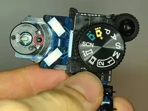
    • To remove the button panel, you have to unscrew these two screws.

    • When reinserting, make sure that the nib for the zoom is in the middle position. Otherwise it will zoom the whole time.

  14. IBkRulNafZ6YNxnm
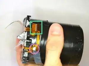
    • Unscrew these 4 screws to seperate the optics part from the rest of the case

    • Unscrew these to loosen the motor from the sensor backplate

  15. iItccE6x5UehnqZS
    iItccE6x5UehnqZS
    bBikiB65O6FEiIee
    bscsjCHiAqK2UiXD
    • Unscrew these 6 screws, after you have taken the optics out of the case. Note that the three motor screws where in place during the photo, but should be removed first

    • To be able to separate the Sensorbackplate from the rest, you have to unsolder the conenctor

    • Also disconnect this connector, as well as the connector on the opposite site

    • Finally you have the sensor with (maybe?) the auto focus lens.

    • If you have dust on your images, it is not necessarily on the sensor. It is rather unlikely because it is enclosed from the auto focus lens. Maybe you should search on other part of the optics first

  16. RLhAe2XMdlqIVrJo
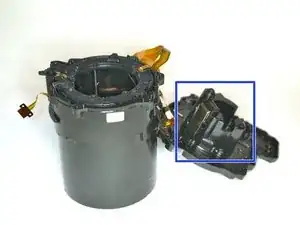
    • The rest of the optics contains 3 tubes as well as 3 moving lenses

    • Unscrew the 4 screw to loosen the sprocket

    • Before you can remove it, you have to floss the 2 ribbon cables through the outer case. It is not easy, you have to rotate them, but it is manageable

  17. 6ZxbIds1waGaXaHC
    6ZxbIds1waGaXaHC
    iSTDvFvqObiMpyHC
    lMYtPkNkeUJkaWTy
    • The outer case has a gear mount and grooves for the inner tube.

    • This tube has the front lens integrated and is visible to the outside when the camera is turned on and zooming.

    • The inner tube moves all 4 lenses.

    • This groove moves the tube with the front lens.

    • The three inner grooves moves the image stabilisation, the shutter and an additional lens.

    • This nip interacts with the grooves in the outer tube.

    • This is the dust and dirt that was stopping the objective from moving out. It isn't much. So, be careful and keep yours clean. I was not able to completely remove it in my camera, but it is working now with some help.

  18. u14PmrQEPib2wabf
    u14PmrQEPib2wabf
    TD6ZaejXh2OmqEIt
    mquZPifsZeBPQYLk
    • Unscrew all 5 screws to remove the rod holder. Then you can separate all three optics groups.

    • This is a moving lens with no other purpose

    • This is the shutter and aperture module. It also integrates some lenses.

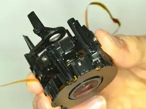
    • This is the image stabilisator, which contains two coils and magnets.

  19. OaotcOnkTsKYIHxL
    OaotcOnkTsKYIHxL
    seKbTdYVOdXCrMpl
    PdqvBIQgSIVqLAPe
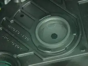
    • The shutter and aperture is combined into one assembly.

    • The shutter seems to be actuated by a magnet.

    • I was able to open and close the shutter with a magnet.

  20. W5UGnvOVNHFc1kiq
    W5UGnvOVNHFc1kiq
    D512pi2v1sZZt1Lg
    CdbOFBIiEY4Bn5R5
    • You can see the two magnets, that are used to move the lens

  21. tG516eth1iWKmaeE
    • These are all disassembled part. Not everything is removed from the case and disassembled entirely

Quanten

Member since: 21/05/18

1016 Reputation

27 comments

Thanks a lot for the instruction. I managed to clean my camera from Sahara-sand. It saved me from a €300 repair bill

han.evers -

Helo ..what kind of bit and size do I have to buy?

Is it ph000?

I Hope

Datyur Natyur -

I’m sorry, but I don’t know, but I would think, that ph000 is too small

Quanten -

I found an IFIXIT size 0 Phillips bit fitted the screws

Bummers -

there is a light ‘'sounds” from the lens part every time I turn it ON it is sounds like broken plastic …. is this common ?

Don -
Thank you for this! I found it very useful in helping me try to repair (unsuccessfully) the dreaded E62:10 issue. I have two requests:

1) Could you expand this to illustrate the insides of the image stabilizer?

2) Could you identify the two small electronic components soldered to the ends of the image stabilizer cable (the parts that fit face down unto the magnets)?

I successfully replaced my image stabilizer cable using your tear down guide, but I did not expect the two small components soldered to the end of the old cable. My replacement did not include them so I was forced to remove and reuse the old ones. My repair failed and I suspect it was because those two components were either bad when I started or ruined by my effort to reuse them. I’d try again but I have no idea what those components are and how to acquire new ones.

Steuman -

Hi, I have not disassembled the image stabilizer during my teardown. I also reassembled the camera and gave it to a friend. I have added Step 19 with all my images, I had from the teardown. But this is all I can provide, I hope you will find a solution

Quanten -

Hello,

Were you able to fix your camera E62:10 issue ?

VMP Peters -

Any idea how to remove the pin that hold the battery door on? I assume the back has to come off, but then how to push the pin out the back is a mystery.

danzeitlin -

Sorry, I haven’t disassembled the battery door

Quanten -

Thanks for this excelent guide!!

matiasrk -

Thanks got everything working again after cleaning out the barrel. Only problem ow is the shutter button won’t take a photo? I guess I need to take all apart again and try to fix it.

Thanks

couldn’t get it back together without your photos

Ernie -

Thank you for guide. I’ve also tried to repair. E62:10 issue. Without success. But I have additional images of stabilizer.

I’ve disassembled image stabilizer. Important parts are conductive tape with some Hall effect sensors and coils.

Coils and hall sensors are in place marked green. Coils are in stabilizer body and sensors on the tape.

Important point are marked red. There are connection points when coils are soldered to tape. When I removed tape I didn’t know about connection points and I cut the glue under the tape with connection wires. Then I’ve very gentle uncovered wires with surgical scalpel. Solder additional short wires to solder the tape.

https://flic.kr/s/aHsmLjSZPy

Mirek Sobczak

Mirek -

part 2.

It is important to unsolder coils wires and remove solder before removing tape

I’ve ordered tape on aliexpress for 6$ for two pieces. I’ve used Hall sensors from old tape. I want to save 120$ (this is the price for reparation in some professional workshop in Poland).

Like I wrote at the beginning I’ve failed but maybe some one will find my images useful.

To author of this guide: fell free to add my pictures to yours teardown if you like.

https://flic.kr/s/aHsmLjSZPy

Mirek Sobczak

Mirek -

Is the image stabilisation cable moving/stretching while zooming? or it is fixed in one place? Because if it is not moving how can it micro-break by itself and cause the e:62:10 error as its being said on some forums.

Stefan -

The image stabilizer is moving while zooming (it has a nib, see step 19, which is gliding in one of the three inner grooves, see step 17, last image) and therefore also it’s ribbon cable.

Quanten -

What type of shutter does hx400v have?

E E -

I have added some detailed pictures of the shutter module. Looks like it is actuated with a (electro)magnet.

I hope it helps.

Quanten -

Hi there. I have a sony HX400v. LCD was intermittant, so have taken out the screen. The fault is with the ms c cable….it has a slight tear. Can this be fixed with super glue or tape? The screen is still functional but faulty, as obviously the movement causes intermittant contact.

Thank you.

Kim Donaldson

Kimdonaldson.1965@gmail.

kimdonaldson.1965 -

Thank you, my friend, for the good instruction. I have the same problem and I tried to replace the ribbon feeding the stabilization system myself. I failed because the coil wires are covered with a solid mass (hot glue?) And it is practically impossible to desolder. Hall sensors are a separate problem. Kidy I tried to carefully desolder it, it fell into 2 parts. Unfortunately, I do not have replacements, so it was mainly the reason for the failure. Nevertheless, for those interested, it is important to pay attention to the 3 white balls on which the mechanism moves when disassembling the stabilization mechanism cover (an action necessary when trying to replace the belt). I just fell out and I was looking for them on the floor for a long time. In summary, the replacement of the tape in amateur conditions is not very possible. But for the persistent - maybe it's worth a try

Leszek Piątkowski -

My pleasure, it is really nice to see, that this guide helps others.

Since the image stabilizer was not the failing part in my camera, I haven’t disassembled it further. It would be very cool, if you could take photos of the interior of the image stabilizer and add these to the teardown (even if some parts are missing, it is a teardown ;) ).

Quanten -

I have changes the optic but now the camera will not start.

I have checked every cable and they are all connected.

But when I push the on/of button, nothing happened

What could be wrong?

Kievit1964 -

I have broken off the blue battery hold down lever. Can the Baseplate be removed (Step 11) without the prior steps, to then remove the Battery Case (Step 12)?

Bummers -

I don’t think so. The baseplate, which covers the battery case, is sandwiched between the mainboard and the rest of the camera. Additionally there are many ribbon cables from the mainboard to the rest. I can’t imagine a disassembly procedure to remove the battery case without removing the mainboard and baseplate.

May put something between the battery and the battery case lid to hold the battery in place?

Quanten -

Gracias por la guía, me funciono a la perfección, a partir del desmontaje de los lentes fue complicado y todo lo ordene!, se me rompieron los cables de la bobina, el flexor del obturador, tuve que realizar reparaciones, pero finalmente remplace el flex del estabilizador y funciono, aun que se me olvido limpiar el lente y quedo con pequeñas basuras :(

Jonathan Mendoza -

PD: Tenia error 62:10

Jonathan Mendoza -

Hi can you find a hack to make the camera do clean hdmi out?

CJ Hall -