Introduction
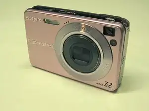
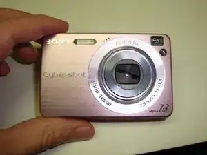
In this teardown, we'll be disassembling a Sony Cyber-Shot DSC-W120 digital camera... in lovely pink! The same steps apply to many W-series Sony cameras, including the W150 used to photograph the teardown. By their very nature, cameras are often exposed to the elements and are easily jostled around or dropped. Unfortunately, they are probably one of the most commonly-discarded items when broken. If you can find the parts, most common camera problems such as a stuck or dirty lens can easily be fixed with a little work. Let's get started!
Tools
-
-
Before disassembling the camera, we'll need to remove the battery and memory card.
-
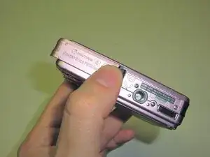
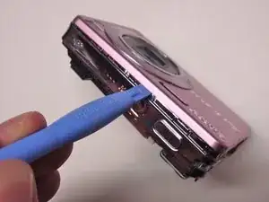
Turn the camera over and gently push the battery door toward the side.
-
The door is spring-loaded and will flip up.
-
Once the door is open, press the battery release and the battery will eject. The battery will then slide out easily.
-
If there is a Memory Stick installed, press it gently and it will eject from the slot.
-
When the battery and memory card have been removed, close the battery door so it does not get damaged during disassembly.
-
-
-
Before we disassemble the main camera, we're going to look at how to disassemble the zoom lens. This is one of the most common parts that becomes stuck or damaged if the camera is dropped or jarred. Dust or debris in this component can also compromise picture quality.
-
To begin, power the camera on so that the lens extends fully. While the lens is extended, eject the battery as described in step one. Otherwise, the camera will retract the lens.
-
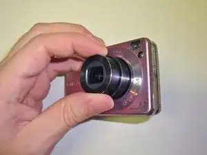
Grip the outer segment of the lens barrel and twist back and forth. I recommend holding the inner segment with your other hand so as not to put too much stress on the lens.
-
The outer cover is attached with a thin strip of adhesive, so you will encounter some resistance.
-
Keep twisting back and forth gently and the outer cover will pop off, exposing the shutter mechanism.
-
-
-
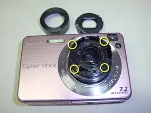
The shutter mechanism is attached to the lens assembly with four tabs. The tabs clip onto the lens assembly at the four points indicated by the yellow circles.
-
To detach the shutter, gently lift the tabs using a plastic spudger.
-
Once all four tabs have been released, the shutter assembly will lift off the lens.
-
Once the shutter has been removed, the outer lens is exposed completely. This is a great opportunity to clean any fingerprints or anything else which might be on it. If you are extremely careful, the inner lens can also be accessed through the openings around the edge.
-
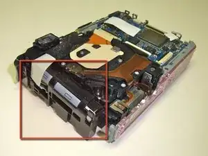
Three of the tabs are identical and of the type indicated by the red box. The fourth is of a different design but is released the same way.
-
-
-
If the camera happens to have a problem (like the one shown) where the shutter does not open or close fully, this can be fixed at this point.
-
Often, simply disassembling and reassembling the shutter assembly will be enough to get it working again. If not, a quick rinse in distilled water can remove any residue or debris which might be jamming it.
-
The shutter is opened and closed by the tab indicated in the green circle. When the camera is assembled, this tab is pushed as the lens extends and retracts.
-
-
-
We're now ready to begin disassembling the camera itself. Fortunately, Sony was nice enough to make all the necessary screws visible and easily accessible.
-
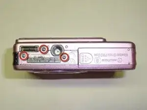
Remove the three identical small Phillips screws on the bottom of the camera.
-
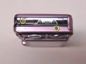
Remove the two identical small Phillips screws on the right side of the camera.
-
Remove the two identical small Phillips screws on the left side of the camera.
-
-
-
After removing the seven screws in step five, the rear panel of the camera is ready to be removed.
-
Gently rock the rear panel until it feels loose
-
Starting from the bottom of the camera, lift the rear panel and hinge it towards the top of the camera. Once you reach a 45 degree angle, the top tabs should release and the rear panel will lift off freely.
-
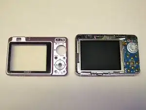
Remove the camera's rear panel and set it aside. The LCD display and the control board are now exposed.
-
-
-
Next, we're going to remove the shiny plastic panels on the sides of the camera.
-
The panel on the lens side of the camera is the easiest to remove. It simply slides toward the back of the camera and lifts off.
-
The right side panel is also quite easy to remove. Hinge the panel slightly towards the front of the camera and it will lift off easily as well.
-
-
-
Now that the side panels are removed, we can begin removing the camera's front bezel.
-
First, remove the two small Phillips screws on the lens side of the camera. These are identical to the screws we removed earlier
-
Using a spudger or small flat-blade screwdriver, gently lift the metal tab on the other side of the camera so that it clears the nub on the chassis.
-
Push the front bezel forward just enough so that the tab does not snap back into place.
-
-
-
The front bezel is attached to the camera's chassis by a number of easy to release tabs.
-
Using a spudger or plastic opening tool and starting at the top of the camera, work your way around the camera's body and release the tabs holding the front bezel to the chassis. The tabs should require almost no effort to separate.
-
The bottom of the camera is a little trickier to get apart. It is held in place by three tabs on the lens side of the camera. Using a plastic opening tool or spudger, work your way along the seam while gently lifting up on the bezel. It may take a few tries to get all of the tabs to release.
-
Once the tabs have been released, the front bezel will simply lift off the camera. The approximate locations of the tabs are indicated by the yellow boxes.
-
-
-
Now that the camera's outer casing has been removed, we are ready to begin disassembling the camera's inner workings.
-
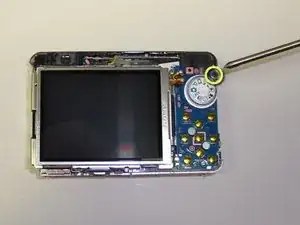
Using a small Phillips screwdriver, remove the single small black Phillips screw just to the right of the mode selection dial.
-
Once the screw has been removed, the entire LCD and control board assembly will hinge up to the right. Be careful as it is still connected to the main logic board by two ribbon connectors.
-
Using your finger or a plastic spudger, carefully lift the black tabs on the two ribbon connectors shown in green. The ribbon cables can then be removed from the logic board and the entire LCD and control board assembly can be lifted free of the camera.
-
The proprietary Sony I/O port connector is attached to the main logic board by a single ribbon cable. Using a spudger, gently lift the black tab on the connector and remove the ribbon cable. The I/O port can now be removed.
-
-
-
Using a plastic spudger, carefully lift up the black foam tape which covers the capacitor leads.
-
Once the pink and blue wires are free, carefully lift the capacitor housing out of the way and set it above the rest of the camera. It will still be attached to the camera but is at least out of the way.
-
-
-
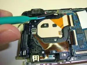
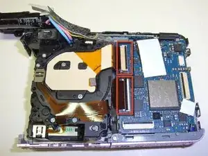
Gently lift the black tabs which hold the two ribbon cables connecting the lens assembly to the main logic board using your finger or a plastic spudger.
-
The lens assembly is held in place solely by the ribbon cables at this point. Once you have removed the ribbons, the entire lens assembly will easily lift free of the rest of the camera.
-
The lens assembly is a sealed unit and I don't recommend opening it unless you have a clean room or don't plan to use the camera again. The pieces inside are very tiny and sensitive to any dust. If it's damaged, it's best to replace this component.
-
To access the CCD, remove the two small Phillips screws indicated by the green circles. If there are any dark spots in pictures, this can often be caused by dust on the CCD. Cleaning it can often help to resolve these issues. Again, you only want to do this in an extremely clean environment.
-
-
-
By this point, very little of the camera is still assembled. Next, we're going to remove the top panel and accompanying electronics. The only things left on the chassis are the battery compartment and the main logic board.
-
With the camera lying face down, begin by removing the small Phillips screw indicated by the red circle.
-
Turn the camera so that you are looking at the front. Using your finger or a plastic spudger, release the tab near the upper left corner.
-
Be careful when removing the top assembly. It is still connected to the chassis via a ribbon cable. Using a spudger, gently lift up on the black tab to release the ribbon connector.
-
You can now separate the top assembly. This assembly contains the flash bulb as well as the power and shutter buttons. The flash capacitor is also connected to it, so be very careful when handling this piece.
-
-
-
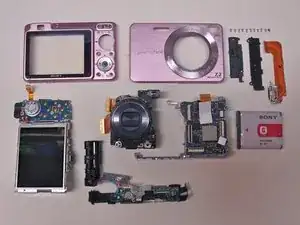
You're done! The camera is now disassembled into its basic components. When you consider how much repair shops charge for labor on cameras, it isn't really that difficult to open it up and replace parts yourself.
-
Some observations and thoughts:
-
There are very few screws holding the camera together. It seems to mostly be held together internally simply by its density.
-
Considering the complexity of its functions, there aren't many actual parts inside of the camera. Most of the largest parts are for interfacing with the user.
-
A pleasant surprise: when I started this teardown, the lens would not extend or retract properly. After simply reassembling/realigning the parts and doing a basic cleaning, it seems to work normally again. Go figure!
-
11 comments
Very good tear down process.
I have a question. I tore down my camera up until I had to disassemble the ribbon cables. I wasn't sure how to disassemble them so I just took a power duster (the can spray) and dusted out around the camera. I assembled my camera and when I turn it on, the screen is white.
What did I do wrong and is there a way to fix it?
Thanks.
Also, I got shocked! hah. It was unexpected. The jolt is pretty strong.
I got it. I apparently disassembled the ribbon that connects to the screen... I hooked it back up and it worked again.
Once again, thanks for the instructions to disassemble the camera! It saved me 140 bucks for repairs.
The first time I fixed the camera without this manual. Lens was stuck so camera reported "lens error message". I opened it completely (and got few shocks from the flash capacitor :)) and when I assembled it again it worked fine.
The next time was by using paper for removing dust between the cylindrical parts of the lens from outside.
Now I did it again but with this time with this manual. I found the problem in the step 3 and 4. One part of the shutter was a bit bended and prevented full opening. It works great again!
oktalv -
