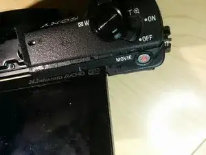
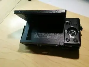
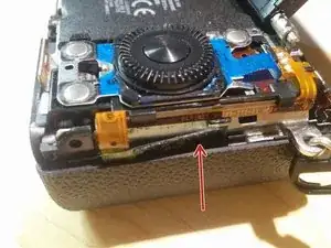
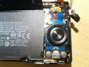
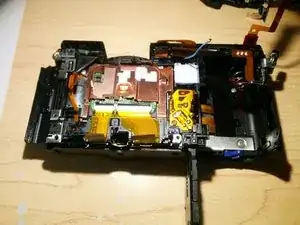
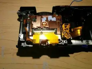
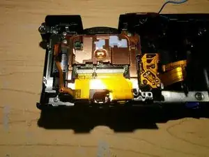
Introduction

You can find spare parts here:

https://sony.encompass.com/model/SONILCE...

I think this is fairly technical and difficult procedure. Please take extra notes!

And keep extra track of all the screws. I won't specify screw sizes since I do not possess that information!

  1. UIRodFVHaKpcGUTB
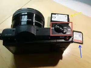
    • Turn your camera off

    • Remove battery

    • Remove memory card

    • Detach camera belt if you have it attached to the camera

    • You might want to disconnect camera lens as well. Just remember to keep your image sensor away from the dust and your own fingers!

  2. lC31A5HCIOFtVnv3
    lC31A5HCIOFtVnv3
    ESDUdDbKdabaWcL3
    FSC2V2yxOAtLNLJd
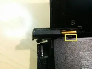
    • Removing single mounting screw of the flash plate cover

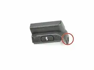
    • Using opening tool or guitar pick pop the plate off. There is a little hook so do not force it! Yellow square shows opening where the flash plate cover hook goes.

    • Gently slide the plate off the camera body. You might have to move display out of the way couple times.

  3. fjQbIM5QyS3wnbpn
    fjQbIM5QyS3wnbpn
    UG5CimaSJZYxnVyg
    JFJYQtVYJqqwwx1S
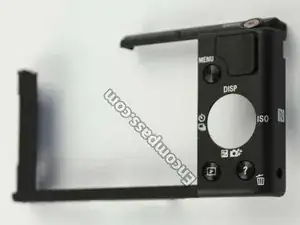
    • First picture illustrates what we are trying to remove

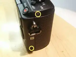
    • Pop the flash. And remove first screw

    • Remove 2 more screws on the side of the body

  4. cRCApDoekJdpP2NB
    cRCApDoekJdpP2NB
    QrJFDBBHqWLdogNf
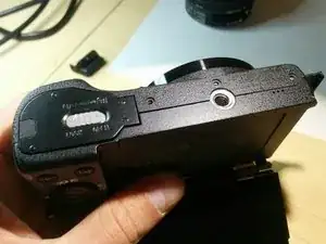
    • Pop the memory card door open

    • Remove 2 more screws

    • Remove 3 more screws from the bottom of the camera

  5. OWPbH14udlNCVYGw
    OWPbH14udlNCVYGw
    aDaWvHi2E2IoK5BT
    Z6liSCLVRX11eA3B
    • Use opening tool, guitar pick (or whatever else) to pop the front plate apart from the main body.

    • Be very gentle!

    • Remove the front plate

  6. BoVbhSBEeXiLalru
    BoVbhSBEeXiLalru
    xA1SSDOkV1PPsPPs
    tZCWO1DZLZKTBKS2
    • Gently separate NFC flex circuit from the body. It might be glued to the body so take extreme care not to damage it!

    • Continue separating circuit down the line. Should be pretty obvious procedure...

    • Remove movie button from the body of the camera as well. Move flex circuit out of the way.

  7. RxKLsfDZjwMZtxlR
    RxKLsfDZjwMZtxlR
    FMWYgmYJN3oYZjgK
    eEwBpHwGFZeLSJPH
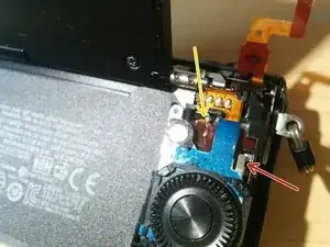
    • Pop little metal stopper of the button panel away from plastic body of the camera. (Look at pictures 1 and 2 to find a difference)

    • Slide the whole button assembly up until you can separate it from the body.

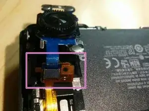
    • Gently pry green flex circuit assembly from the middle body. See picture #2.

    • Now you can remove button panel flex circuit from middle body flex circuit. (Read: blue flex from green flex). And separate button panel completely from the camera!

  8. TIQtQpTVtTZUf5IR
    TIQtQpTVtTZUf5IR
    mkPAHetIS3SZanOM
    QQ2y1BSSsMKLbb3H
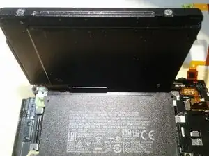
    • Remove 2 screws holding LCD screen assembly

    • Pry LCD screen assembly away from the camera body. Use opener tool, guitar picks, whatever. Be gentle!

    • Carefully move LCD screen away from the body. It will be still connected to the PCB via flex circuit!

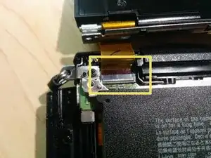
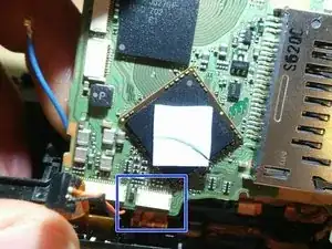
    • Pop little latch of the LCD screen connector and gently disconnect LCD screen from the camera body.

    Do you know how to replace the display panel? My camera fell down and it seems like either the display itself or some connector isnt working. Display shows only "wild color pixels". Got a new display panel and tools only and trying to replace it now. Thanks in advance!

    Martin Hiel -

    Yeah, just follow this guide to the step 8 and reverse procedure for the assembly process. Have fun!

    Kirill -

    How to pop little latch?

    Chatphong -

    Use a guitar pick to pry it open

    Kirill -

    Hey,

    Do you have more details of how to “pop the little latch” of the LCD screen connector? Maybe a video somewhere?

    I searched everywhere and can’t find anything. I have no idea how to disconnect this particular flex cable connector.

    Thanks!

    James Hustle -

    The “latch” for the display flex cable is in fact the thin strip on the OPPOSITE side to which the flex cable goes in. NOT THE WIDER PART. To release, or “pop”, the catch gently get your finger nail or small plastic tool under the edge of this on the side OPPOSITE where the cable goes in (the edge NEAREST the BOTTOM of the camera) and GENTLY prise upward. It hinges up towards the flex cable.

    To re-insert, the catch must be UP (vertical), slide the flex cable in CAREFULLY as far as it will go. Then while keeping it in position, GENTLY push the catch to rotate it down towards the bottom of the camera.

    George -

  9. 5YUX41nQkqUmqICI
    5YUX41nQkqUmqICI
    SUFAnrhleZWfClt5
    BLTwHMfmQHVO1eSU
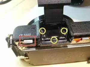
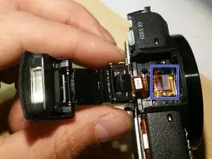
    • Pop flash once again. You won't have actual button but you still have metal lever to do so.

    • Unscrew 3 screws that attach flash to the camera body.

    • Gently move away flash from the body. Disconnect flash flex circuit from the camera body. No latches this time!

    • Carefully slide flash tray out of the camera. See last picture illustrating tray mid way out of the camera. Pull the tray completely away from the body.

    When replacing a failed flash unit with new Sony spare, DO NOT THROW THE OLD ONE AWAY.

    When you undo the two screws which secure the top cover of the flash - which does NOT come with the spare flash unit - you will see a small rectangular metal contact on the left side of the flash tube (when viewed as in the first of the three pics above). This is NOT a contact, it is in fact a very small neodymium magnet. Replacement flash units (including genuine Sony ones) do NOT come with this magnet.

    When fitting a new flash you need to gently prise this magnet out of the old flash and fit it in the same position on the new flash - it is just a press fit - BEFORE you fit the top over.

    If you DON’T transfer the magnet from the failed flash to the new one, the camea can’t detect when the flash is closed. This results in the flash triggering even when closed.

    George -

  10. kQCDDKHT2Dp2KyH1
    kQCDDKHT2Dp2KyH1
    AOJhGNcyaVni4oVv
    SMPeqk2jZl5xkxQf
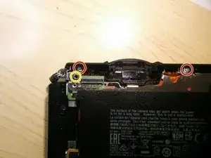
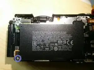
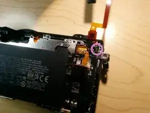
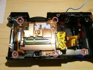
    • Remove 2 screws

    • Remove 1 screw. I am not 100% sure but I think it is black one. The rest of them are silver.

    • Remove yet another screw

    • And the last screw, tucked away behind the frame. Might require pretty skinny screw driver...

    Hi there,

    I've removed all the screws, but the top left corner wouldn't come off!

    Any help?

    Thanks

    Rayan Phenix -

    I have the same. Have you got idea for top left corner ? My screw is on the bottom, not as on photo!

    Daniel O -

    pull rectangular flash until completely removed from camera to find top corner screw.

    Tabria Williford -

    I guess they might have variations or I might of left a screw undocumented

    Kirill -

    Has anyone come up with a solution? I have the same problem with the upper left corner solidly stuck in. I have levered it up a few mm on the outer edge but the inner part seems solidly stuck. No screws I can see to remove.

    Fred S -

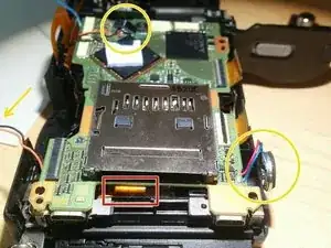
    Be sure to remove the flash try. It is another piece, it brings the metal flash button with itself. Behind it you'll find the last screw, in the image is circled in red. After the 5th screw is out, the mid frame will slide out.

    Renato Carena -

  11. im2JiRDSHFAKRrMT
    im2JiRDSHFAKRrMT
    JHPMQaQ6NTARMwRU
    vGretQptUBhOgFts
    • Gently pry the mid frame from the body. Make sure all the flex circuits are out of the way. This step might be tricky. The frame might be glued so take extreme care not to damage anything!

    • You probably do not have to remove camera mount. But I did so anyway!

    • You probably won't have to remove camera belt clip either. I would recommend using it as extra leverage while removing mid frame from the body.

  12. U1oCgafbMvELEXY2
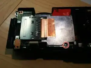
    • Unscrew single heat sink screw.

    • Detach sticker from the memory card connector.

    • Remove heat sink. It might be glued with thermal paste to the motherboard.

  13. VKMGKDJpRYhHZyW6
    VKMGKDJpRYhHZyW6
    KnFNbgyLnquKNNYh
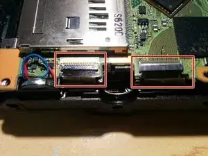
    • Open latches using guitar pick or opening tool.

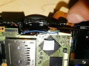
    • Disconnect image sensor flex circuits from the motherboard.

    • Gently pry flex circuit from the connector! Be careful to apply just enough force!

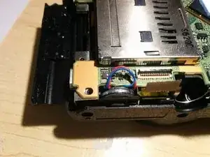
    • You may pull the speaker out of the enclosure using tweezers while you are working around this area.

  14. XtScJOICQadrRCiV
    XtScJOICQadrRCiV
    GEaFxlYwZ1Wf6TEf
    LcRZNYkQY2m2PV1c
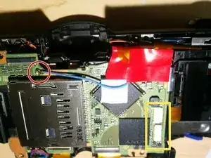
    • Disconnect WiFi antenna cable. Very gently pry it off!

    • Disconnect 2 camera lens flex circuits in the right bottom corner of the mother board. No latches here!

    • Lift masking tape away from the mother board. Most likely your masking tape is going to be black not red!

    • Disconnect 2 more flex cables. One of those is power flex circuit and the other one is either flash or buttons flex circuit.

  15. ujBcWMeHwqRpQFo6
    ujBcWMeHwqRpQFo6
    IZLMvausmYKhfkJZ
    3giXTBesmMGvBPWM
    • Disconnect shutter flex cable from the bottom side of the mother board. No latch here. Gently pry it off! I bet you are master at disconnecting those off by now!

    • Make sure that both microphones and speaker is out of the camera body at this point.

    • Disconnect one more flex circuit connected to the bottom of the mother board. No latch here. It is either flash or buttons flex circuit.

    • Remove motherboard.

  16. JVW3VRsRnCwkywqE
    JVW3VRsRnCwkywqE
    GK4IuraWSXioC3LZ
    OkMl2JnqCEYsIZyW
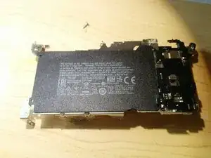
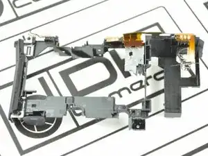
    • Gently remove plastic body assembly. Pay close attention to the flex circuits around the body. Make a note which ones supposed to stay with the body frame and which ones stay with the front assembly.

    • Plastic body frame is shown in the last picture. It is shown without battery door. You don't have to remove battery door!

  17. 2fvdkNEaM3IaGWtU
    2fvdkNEaM3IaGWtU
    iWCjjCS5oVtFQxXP
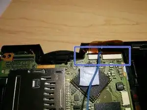
    • Open latches first. Gently remove both flex circuits attached to the image sensor. Take a note which one goes where

  18. 2OYWb4ym1mNifB5B
    2OYWb4ym1mNifB5B
    c6lIyKXVdKaCGjUA
    Wh4l4fjJn45Y1COg
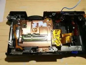
    • Remove 5 screws

    • Remove Front Metal Frame

    • Remove Image Sensor Assembly

    • You can continue disassembly if you want to separate image sensor from the shutter. I have not gone that far but I am sure it should not be too difficult to figure out.

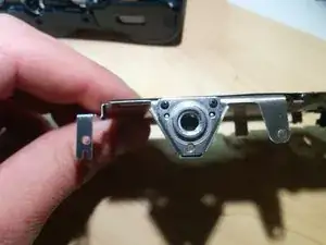
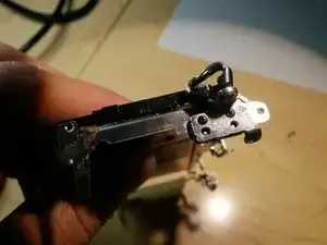
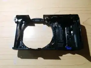
    • Last picture shows front case of the camera. It does not include flex circuit. You should have flex circuit still attached to the front case!

    • Note how camera belt clip is still attached to the front case of the camera. You don't have to detach it!

    Hi, thank you very much for detail instructions. I got some error message in my a5000 and this instructions set helped a lot to open up my camera. However, at this stage, I needed to further open up the sensor circuit to fix the spring latch inside that is connected to shutter. It could be fixed easily. But them while I was assembling the camera back, I found the following part that I cannot remember at all how/where to be connected. I cannot even figure it out where it came from. Altogether 3 metal frames I found from the sensor unit and I found how two of them can be set back, but this is the one I cannot figure out where/how to be set back. Please help me if you can. I understand the camera model is different but they have a lot of similarity.

    https://www.dropbox.com/s/r571jnr3yprv4z...

    https://www.dropbox.com/s/juuyf66myaasir...

    Please let me know if you need more picture.

    Thank you very much.

    Mahmudul Faisal -

    Kind of looks like cover for the shutter but I am not sure. Does it work without it? It looks like it does not serve any electrical purpose, strictly mechanical…

    Kirill -

    I also think similar. It is entirely mechanical. I paused my assembly there. I will try to assemble without it to see it works or not.

    Thanks for your reply.

    One guess, it seems that you are not sure of this component. So, either it is exclusively for a5000 model or it is from some area that you did not open. What do you think?

    Mahmudul Faisal -

    Exactly! I might of stopped too early! And yes different model should have different assemble/disassemble procedure! Good luck!

    Kirill -

  19. sayJWVJFg6RmU6hy
    • Reverse previous steps to assemble the camera! Pray you did not forget anything otherwise you camera won't be working properly!

    • I ripped one of the flex circuits while disassembling my camera. I got it replaced. I did not have this guide so I hope you won't make same mistake that I did!

    • Have fun! And good luck if you need it!

Kirill

Member since: 11/04/17

1550 Reputation

19 comments

Hi, Kirill

I have teardown the 5100 . I’m trying to light the camera so that could beinstall in UAV.

It could be work at very beginning of teardown. I removed the useless part, such as the LCD, flash light, and heavy frames. After that I get a test. It could work still.

But with a weekend pass by. It cant work any more.

It look like short circuit.

when I try to open the camera with a full charged bettery. it won’t work. this process cost 3 seconds.

and then I measured the voltage of the battery. It’s voltage is 0. charge the bettery with 5 seconds. back to full charged(through measured voltage).

I have no idea with this situation. What should I do?

Would you please help me?

You can email me if convenience. email: jason.190@163.com

Thank you very much!

Jason

Jason Zhang -

Hi Jason,

Yeah, I am not sure what the problem is to be honest. I don’t think this camera have been designed to work half disassembled .

I would look for more appropriate camera. Sounds like you might have short circuit somewhere. You might have to replace one of the internal boards. I am not sure, you would have to debug to see which one failed.

Anyway, best of luck

Kirill

Kirill -

Hi Kirill! So I have a problem with my Sony a5100. Whenever I half press my shutter button or zoom using the lever below the shutter button,my cam will turn off all by itself and I need to press the shutter button for like 5 seconds for the screen to turn on. Do you have any idea what’s wrong with my cam? Please help.
Clea Banal -

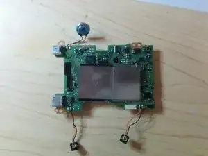
Thank you, thanks to this instruction I replaced the PCB board in my camera.
luchschen -

I followed a youtube tutorial looking for a way to fix the overheating issue in my a5100... I did it correctly, at least the disassembly part. The big misconception comes up at the LCD screen ribbon cable part of this tutorial. The guy in the video claims that the conector where's the ribbon cable fits, is friction fit... IT'S NOT. I've learned it by the hard way. As it’s shown here, that is a flip up conector.

Keeping it short, i ruined the LCD screen ribbon cable and maybe the LCD screen connector in the board too, the contacts in both to be specific. Or that was my initial thought.

Where I live is almost impossible to find, at least, a decent technician but I found a good one outside the city. It cost me a bit expensive but he made it, with a drawback, the LCD screen shows signal but there’s a bizarre green/yellow color form where it's supposed another color has to be in.

At this point i was working with what i have, but i really wish that there’s a way to recover the full correct function of the LCD screen.

Omar chacon -

Yeah, it's tricky for sure. I didn't have a guide when I took my camera apart and I ripped one of the flex circuits as well. That's the price of the learning process.

Best of luck,

Kirill

Kirill -

I really don't want let go my a5100. Do you think maybe there is a way to get back the full function of the LCD screen? I don't know so much about circuitry and often don't have the right tools but i really get compromised with the things i do. Can you give my a hand? :D

Omar chacon -

Omar, you can probably replace LCD screen. If you ruined flex circuit.

And connector if you ruined it! But replacing connector would require some soldering skills and tools. And without proper tools and experience you are risking to ruin the board that that connector attached to. You would still have to find exact make and model of that connector. So it is by far harder to accomplish. I don’t know what to tell you. You can try finding someone who is handy with soldering or buy the whole shabang and practice on older electronics until you are confident you can pull this task off! Good luck! :)

Kirill -

Is there a way to remove the HDMI-Cover-thingy without breaking it so I can reattach it later? I am using the a5100 with a Zhiyun Smooth 4 + adapter and using a phone as monitor is far from great. I’d like to connect a fieldview monitor but the cover is in the way. I don’t want to just rip it off :-/

Thanks!

Alexander Graetz -

Kirill

I don't see a step that describes how to remove the sd card slot door. The door broke on mine and i can't figure out how to replace it. I have the front panel off but don't want to go any farther if i don't have to. Any help would be appreciated.

Shaun Jeffs -

Wanted to thank Kirill and the other contributors for this guide!

I replaced the Rotary Button Panel easily thanks to this guide, all I spent was 25 bucks to purchase the part from china. A service shop was charging me $135 for this job…

Thanks again.

ED.

Eric De los santos -

Anyone else has issues with the LCD screen not coming on after reassembly? I don’t think I broke it and even bought a replacement. I’m wondering if there was something else I missed. Any ideas on what to check?

Jared Kotoff -

Hello man, idk if someone is going to answer here, i have a 5100 and my flash wont stay closed. Can anyone help please?

Consta C -

I have a5100 won't power on. Checked voltage of battery it is 7.9V good.

Anyone know if I can replace a fuse somewhere or replace main Pcb? Or….. also, I can solder.

Timbo Yuen -

I just want to replace my a5100 front case. But it seems like its the last part of this disassembly. Which parts can I skip before I can remove the front case? What should I be careful of if im going to remove the front case? Thanks

Tawin Malimban -

Hello I have an alpha 5100 and there is a dark spot in every picture in the same spot no matter what lens i have on it. Would this be dust on the inside or a bad pixel?

Chad Does everything -

Couple of comments to add to this:

The “latch” for the display flex cable is in fact the thin strip on the OPPOSITE side to which the flex cable goes in (nearest the bottom of the yellow rectangle in the pic). NOT THE WIDER PART. To release, or “pop”, the catch gently get your finger nail or small plastic tool under the edge of this on the side OPPOSITE where the cable goes in (nearest the bottom of the yellow rectangle) and GENTLY prise upward. It hinges up towards the flex cable.

To re-insert, the catch must be UP (vertical), slide the flex cable in CAREFULLY as far as it will go. Then while keeping it in position, GENTLY push the catch to rotate it down towards the bottom of the camera.

Also:

When replacing a failed flash unit with new Sony spare, DO NOT THROW THE OLD ONE AWAY.

On the left side of the flash tube (under the top cover) is a small magnet.

If you DON’T transfer the magnet from the failed flash to the new one, the camea can’t detect when the flash is closed.

George -

OK - part number for official Sony replacement flash unit for ILCE-5100 camera is 149279515.

You can find that on the webite for eetgroup, Sony’s official UK spares distributor. If you are a consumer, they will direct you to another outfit in the UK called Your IT Delivered who sell them on line.

There are a couple of points to note when replacing a failed flash which I’ve added to the teardown

George -

I want to replace the turn on/off button specifically and I have a donor shell. The shell is like a one piece so I'm wondering is there a possibility to disassemble the turn on/off switch specifically from the front plate?

Tom -