Introduction
SSL2 is the first audio interface from Solid State Logic, which is famous for its large analogue mixing consoles. What components did the legendary company use and how does the mysterious 4K button work?
What did I miss? Please leave a comment below.
Tools
-
-
SSL 2 is a very straightforward audio interface that is easy to use and intuitive. Each function has its own analog control. Its a pleasure to use.
-
The audio quality as ADC is excellent. The preamplifier is very low-noise and the gain is sufficient even for dynamic microphones that are difficult to drive.
-
DAC is also very good, but not high end (compared to NAD D1050). I notice the difference especially in the bass response.
-
The headphone amplifier lacks a little power at high volumes (adds some distortion), but is sufficient for most applications.
-
-
-
First remove the four top screws holding the top panel and the four screws at the back holding the back panel. Pop the interface out of the housing.
-
The board is held by massive stand-offs which help to avoid flexing. There are no screws here.
-
The housing is made of very solid and massive ABS. Nothing else can be seen or serviced from the bottom of the unit.
-
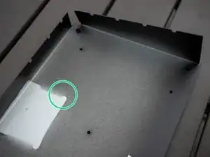
The bottom plate is made of ca. 1mm thick, painted steel sheet.
-
The unit is very easy to open and to repair. Nice!
-
The unit weighs 880g. This is a lot for a sound card in a mostly plastic case. This weight and robustness are achieved by using a metal plate and an unusually thick ABS plastic case.
-
-
-
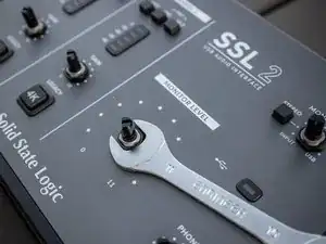
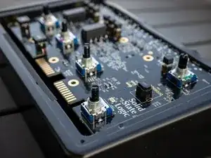
The PCB is attached to the upper aluminium plate by nuts on the pots.
-
Use the 11 mm wrench to loosen the nuts.
-
-
-
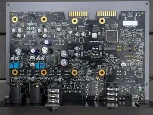
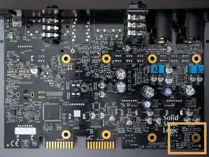
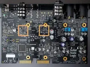
The PCB is all black and has gold plated contacts and vias. SSL has two versions of this interface: SSL 2 and SSL 2+. The "+" version has more outputs and offers MIDI connectivity. For this reason, many components are missing from the circuit board shown here. Obviously, SSL uses the same PCB for both versions of the product.
-
Although the input sockets are combined XLR/TRS, the signal paths are separate. Nice!
-
SSL uses high quality, mostly Japanese, components (Alps, NJM, AKM, Nichicon, Panasonic) throughout the product. The connectors are made by Neutrik. Nice!
-
-
-
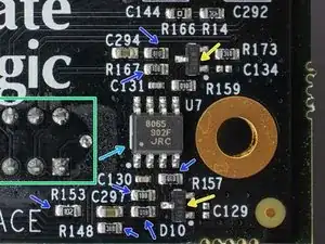
NJM8065 (labelled 8065 902F JRC) by Japan Radio Company. High-gain, wide bandwidth, dual operational amplifier. Data sheet.
-
The NJM8065 combines many of the features of the NJM4558 as well as providing the capability of wider bandwidth (10MHz typ.), and higher slew rate (4V/μs typ.) make the NJM8065 ideal for active filters, data and telecommunications, and many instrumentation applications. (From the data sheet)
-
BAR 43S STM. Small signal Schottky diode.
-
There are several resistors in the circuit: 188: 1.8 GΩ, 018: 100 MΩ, 102: 1 kΩ, 010: 1 Ω.
-
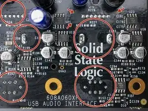
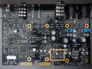
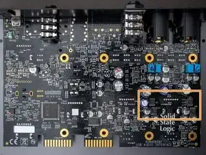
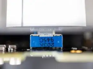
4K switch soldering points.
-
The PCB was not properly cleaned of flux residues after soldering. High quality products are usually very clean.
-
The 4K Legacy circuit is boosts higher frequencies and adds harmonic distortion to the sound. This analog effect can work well in live broadcasts with darker microphones such as the Shure SM7B. On the other hand, the 4K circuitry seems to introduce more noise into the signal. I recommend leaving it off for high quality recordings.
-
-
-
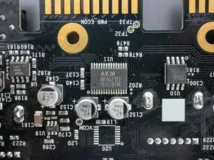
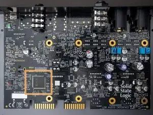
AKM AK4621EF CODEC by Asahi Kasei Microdevices. 115dB 192kHz 24-bit 2 ch ADC & 2 ch DAC with Low Latency Digital Filter. Website, Data sheet.
-
The AK4621EF is a high performance 24-bit CODEC that supports up to 192kHz recording and playback. The on-board analog-to-digital converter has a high dynamic range due to AKM’s Enhanced Dual-Bit architecture. (From the data sheet)
-
The DAC utilizes AKM’s Advanced Multi-Bit architecture that achieves low out-of-band noise and high jitter tolerance through the use of Switched Capacitor Filter (SCF) technology. (From the data sheet)
-
-
-
XMOS XU212-256-FB236 (marked XMOS U11280C20). xCORE Multicore Microcontroller. Standalone real-time RISC processor. Data sheet.
-
This is the actual interface which manages the whole I-O work and timings.
-
The xCORE200 Series is a range of 32-bit multicore microcontrollers brings the low latency and timing determinism of the xCORE architecture to mainstream embedded applications. xCORE multicore microcontrollers execute multiple real-time tasks simultaneously and communicate between tasks using a high speed network. (From the data sheet)
-
-
-
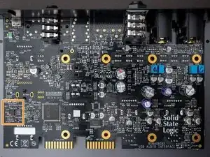
MXIC MX 25L8006E M2I-12G, 8MBit SPI Flash, SOIC-8 CMOS Serial flash. Data sheet.
-
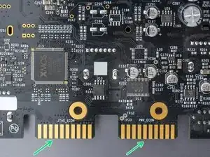
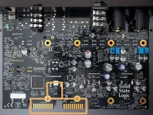
The 10 lines JTAG and PWR connectors are most probably used for flashing the device during production.
-
Those connectors are suspicious: Solid State Logic uses the same connectors for their 500 series console modules. Can the interface be used in a different setting? All connections seem to go somewhere.
-
-
-
NJM8068 (marked 8068 906F JRC) by Japan Radio Company. Low noise bipolar input dual audio operational amplifier. Website, Data sheet.
-
The NJM8068 features Low distortion, high slew rate, wide bandwidth and high open-loop gain. In addition, unity-gain stable allows voltage-follower operation. These features make NJM8068 ideal for audio pre amplifier, microphone amplifier, line amplifier and other audio applications. (From the data sheet)
-
-
-
NJM8080 (marked 8080 945F JRC) by Japan Radio Company. Dual operational amplifier designed for high quality audio applications. Data sheet.
-
The NJM8080 features high resolution and crispy-clear high frequency sound, which can fully perform the digital sound source with loss-less. NJM8080 features low noise, wide gain-bandwidth, low distortion and high output current, and various reliabilities and conveniences are improved. (From the data sheet)
-
-
-
OPA1678 (marked OP1678) by Texas Instruments. Dual channel low noise low distortion operational amplifiers. Data sheet.
-
The OPA167x amplifiers achieve a low 4.5-nV/√Hz noise density and low distortion of 0.0001% at 1 kHz, which improves audio signal fidelity. They also offer rail-to-rail output swing to within 800 mV with a 2-kΩ load, which increases headroom and maximizes dynamic range. (From the data sheet)
-
The OPA1678 and operate over a very wide supply range of ±2.25 V to ±18 V or (4.5 V to 36 V) on only 2 mA of supply current to accommodate the power supply constraints of many types of audio products. These op amps are unitygain stable and have excellent dynamic behavior over a wide range of load conditions. (From the data sheet)
-
The OPA167x amplifiers use completely independent internal circuitry for lowest crosstalk and freedom from interactions between channels, even when overdriven or overloaded. (From the data sheet)
-
-
-
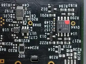
NJM4556A (marked 4556A X17L JRC) by Japan Radio Company. Dual operational amplifier. Data sheet.
-
The NJM4556A integrated circuit is a high-gain, high output current dual operational amplifier capable of driving ±70mA into 150Ω loads (±10.5V output voltage), and operating at low supply voltage (V+ /V- =±2V~). (From the data sheet)
-
The NJM4556A combines many of the features of the popular NJM4558 as well as having the capability of driving 150Ω loads. In addition, the wide band-width, low noise, high slew rate and low distortion of the NJM4556A make it ideal for many audio, telecommunications and instrumentation applications. (From the data sheet)
-
-
-
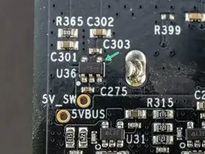
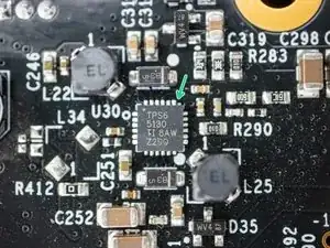
TPS65130 by Texas Instruments. Split-Rail Converter with Dual, Positive and Negative Outputs. Data sheet.
-
ON 842B Zener Diode.
-
27 comments
One of the best user-made teardowns I’ve seen so far! Congratulations on making your first one!
CChin -
Very nice photos! As a pro EE though, just wanted to correct a few misconceptions in step 6:
Flux: if they used the right type of flux, leaving it on is fine. Many switches and potentiometers can’t be “washed” because they’re not sealed (the liquid would get stuck inside), so after SMT assembly and cleaning, these are usually hand-soldered separately using “no-clean” flux - this class of fluxes is non-corrosive and safe to leave on the board permanently. The only reasons to clean flux off the board are DC leakage currents (which only matter for pA or fA measurements, nothing in the audio realm will matter at all in this way) or corrosion (if you’re not using a no-clean flux).
Resistor values: definitely no gigaohm values; leakage around the resistors is probably in the gigaohm range. These are using the EIA-96 style resistor codes, which are standard on 0603 and smaller - I can see how it would be easy to misread the “B”s as “8”s. The schematic for each channel looks something like this.
DCS -
nice post! thanks man


