Introduction
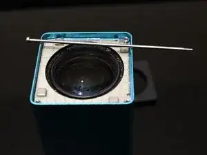
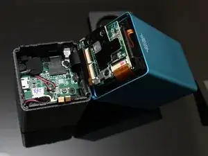
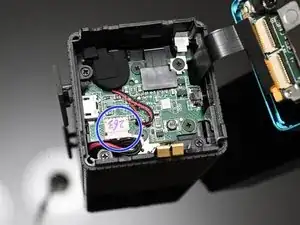
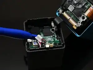
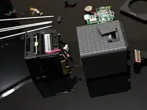
This guide show you how to take a first generation Lytro camera completely apart, all without causing any damage. I've seen some other guides, but none of them explain how to reattach the camera lens cable. If you take the camera apart using the steps provided in this guide, you won't even have to ask how to reattach the cable. I believe this is the proper disassembly (i.e. the reverse of how it would have been assembled at the factory.)
Tools
-
-
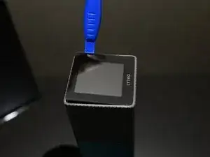
Insert a plastic spudger between the rubber trim and the edge of the screen.
-
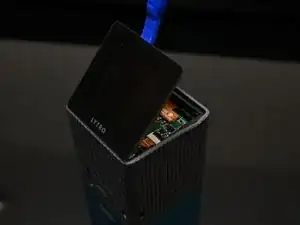
Gently pry at the edges of the screen until it begins to pop out. It is held in with a rubbery adhesive.
-
-
-
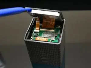
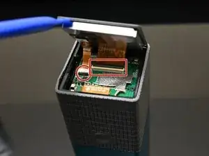
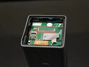
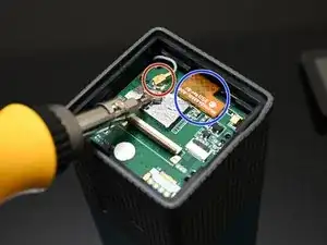
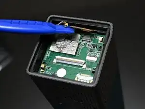
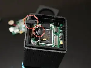
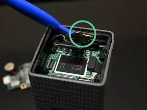
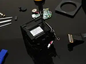
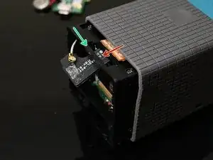
Remove the antenna cable. This is covered with conductive tape which you will need to partially peel away.
-
Remove the zoom control ribbon cable. This one is just snapped into a connector on the board. Gentle prying will remove it.
-
-
-
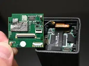
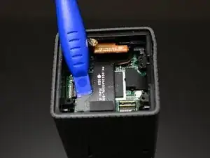
Pry the board out.
-
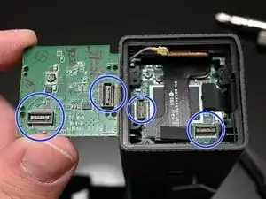
Note that this may require a spudger or a small flat tip screwdriver due to the board-to-board interconnects on the back.
-
-
-
Flip the camera upside down. We need to work on the lens side now.
-
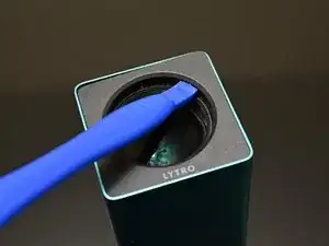
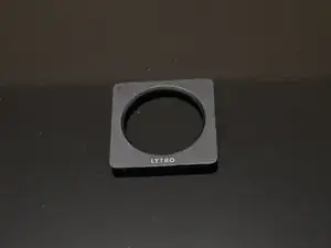
Insert a spudger between the lens and the plastic trim on the front of the camera.
-
Pry up gently to break the adhesive and remove the face plate.
-
-
-
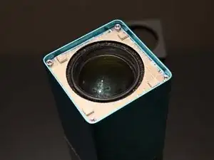
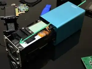
You can now open the camera by breaking it in half at the seam between the rubberized grip and the anodized lens housing.
-
-
-
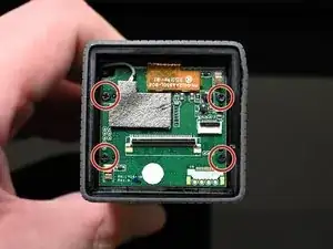
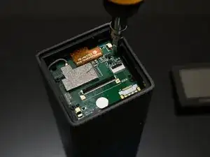
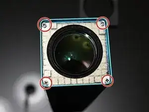
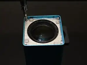
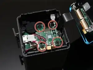
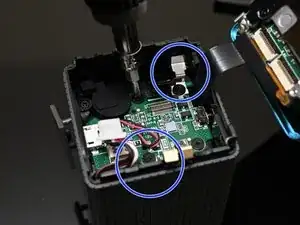
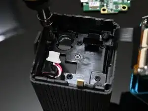
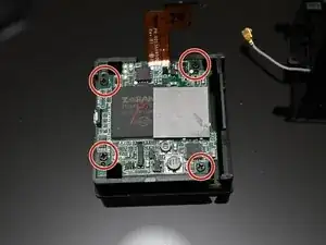
Remove the four screws that hold this board in.
-
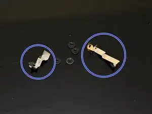
Pay special attention to the two screws which retain metal... things. One of these is definitely required for proper grounding/RF compliance (not sure about the other). Do not lose these.
-
-
-
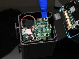
Pry the board up gently.
-
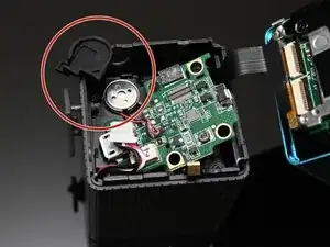
Remove the rubber cap from the speaker.
-
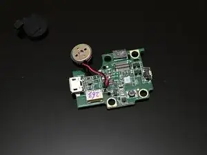
After removing the speaker cap, the speaker is just held in with adhesive and can be gently pried up.
-
Once the speaker is free, you can safely remove the board.
-
-
-
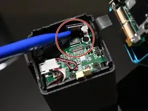
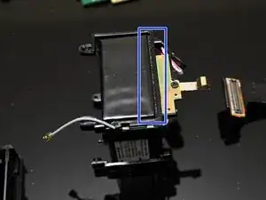
Remove the foam pad from the back of the lens/sensor cable.
-
Be careful to watch for how the zoom control ribbon cable and the lens/sensor cable are moving as you push this next sub-assembly out.
-
Push the battery/CPU sub-assembly out gently from the lens side (i.e. toward the screen side) of the camera.
-
-
-
After pushing the CPU/Battery assembly out, we need to remove four screws to separate the CPU board from the battery assembly.
-
-
-
The CPU board is held onto its frame with four screws. You may remove these if you need to replace the CPU board.
-
The battery is held onto its frame with some adhesive foam. You can cut this foam with a knife to remove it.
-
-
-
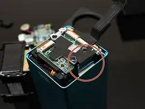
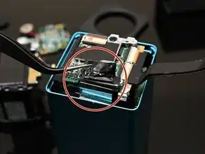
At this point, the only thing holding the lens assembly in its housing is a single piece of tape. The adhesive is not strong. Lift it with a pair of tweezers or the like.
-
After the tape is lifted, the lens assembly can be pushed out from the back (from the screen side of the camera).
-
-
-
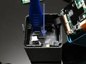
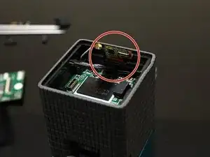
The zoom control ribbon cable is tricky to get back in position. It needs to be threaded through a hole in the battery/CPU sub-assembly housing.
-
Start with the cable on the outside of the housing, then tuck it through the hole pointed to by the red arrow.
-
After tucking it into the hole, the cable should be poking out underneath the plastic support pointed to by the green arrow.
-
Be mindful of the board-to-board interconnects when replacing the interface board. There are plastic pins which help align the board, and the screws should apply enough pressure to snap the connection together, but you may want to make sure that they're together by pressing gently behind the connectors until you hear them click.
-
