Introduction

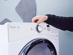
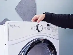
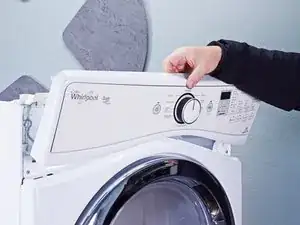
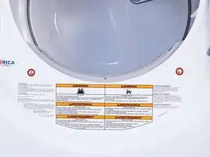
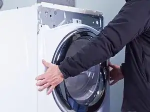
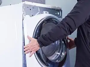
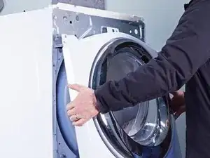
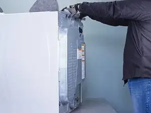
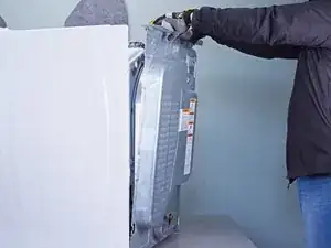
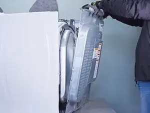
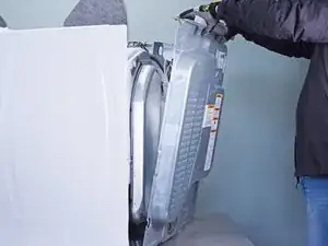
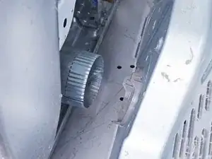
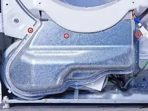
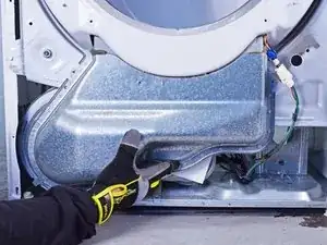
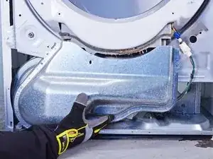
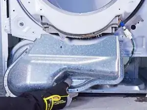
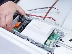
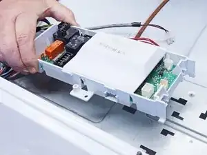
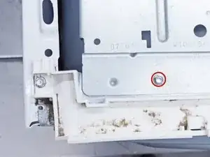
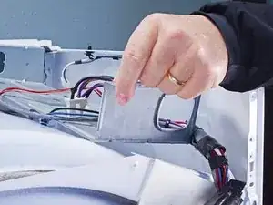
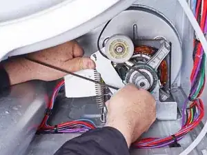
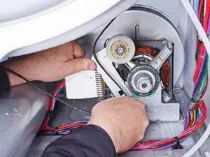
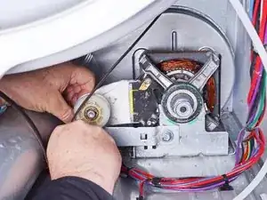
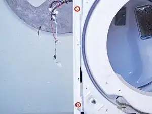
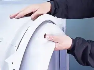
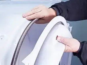
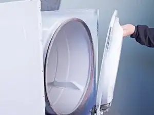
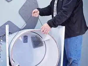
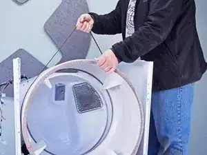
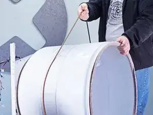
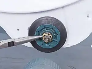
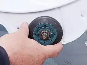
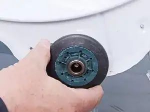
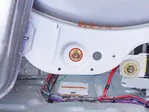
Use this guide to replace the drum roller assembly (drum rollers and roller shafts) on your Whirlpool dryer.

The drum rollers serve as the bearings for the drum so that it tumbles freely. When they wear out or fail, they will make a rumbling or squeaking noise. The noise will be fairly loud, as the drum roller shafts are strongly mounted to the chassis of the dryer.

The drum rollers are best replaced as a set. If one has worn out, there's a good chance that the others will follow since they all have bearings in them.

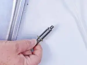
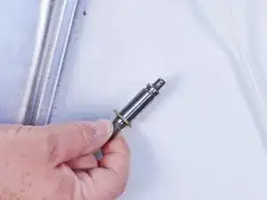
Check the drum roller shafts for wear when you are replacing each roller. If you see wear marks but cannot feel a groove with your fingernail or fingertip on the shaft, it's probably still serviceable. The shafts only require replacement if they're damaged.

This guide will work for most Whirlpool dryers. This guide is written with a model WED87HED dryer. If you have a different model, you may encounter some minor disassembly differences, but the overall repair process will be the same.

  1. cRUlfkgf2YwoDST3
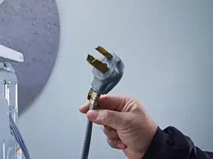
    • Before you begin your repair, unplug your dryer.

    • Your power cord may have four prongs rather than three. The additional prong is a ground connection.

  2. u4WTU4KTBjf1GgPm
    u4WTU4KTBjf1GgPm
    KmGeNIaHMQTiHSWW
    UyNbTg6t3WxLV6FM
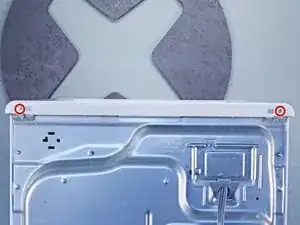
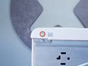
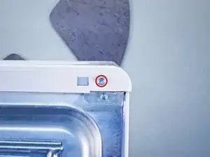
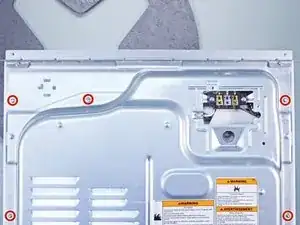
    • Throughout this guide, keep track of each screw and reinstall it exactly where it came from.

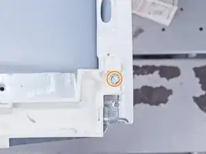
    • Use a nut driver to remove the screws securing the top panel to the rear panel bracket.

  3. gbDdHJLNo1Iiq3Y1
    gbDdHJLNo1Iiq3Y1
    vxW1WX6cffbgMuaD
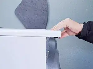
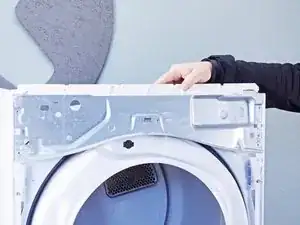
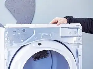
    • Grasp the top and slide it 1/2 to 1 inch toward the rear of the machine.

  4. 2iNpUqjOIuDIiEQU
    2iNpUqjOIuDIiEQU
    IkW1XSsjMSmLOsT2
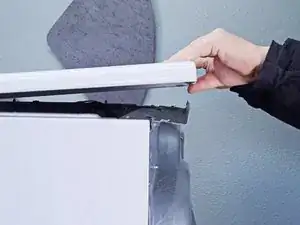
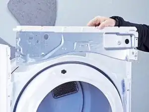
    • Lift the top panel upward to separate it from the chassis.

    • Remove the top panel from the machine.

  5. 4EqwYWjHdXpSDP2P
    4EqwYWjHdXpSDP2P
    I5XdQIMZQChnl4Ap
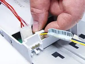
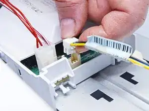
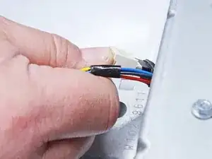
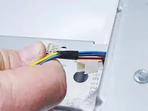
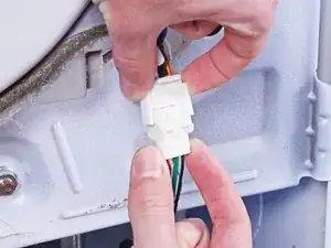
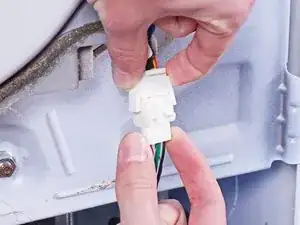
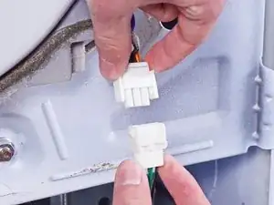
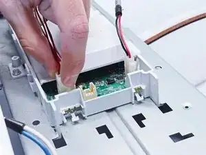
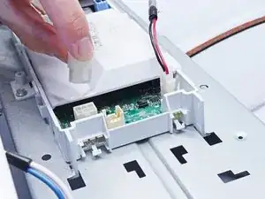
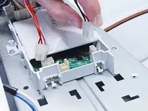
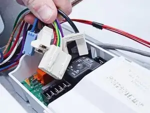
    • Disconnect the control panel cable from the main board.

  6. O21IMM2KKfDgSXgW
    O21IMM2KKfDgSXgW
    2i3v6ir4JGoNnvAC
    • Disconnect the drum light connector.

  7. vgpvSUy3LVl3MKa2
    vgpvSUy3LVl3MKa2
    5KH3EZG4GCmRwFVH
    • Remove the screws securing the control panel.

  8. oZUJsARu4qoKMFBq
    oZUJsARu4qoKMFBq
    OQBZEtdPmGqahirE
    kBuvEfxxfEZJiHPk
    • Lift the control panel up and tilt it away from the chassis to remove it.

    • Make sure to thread the cable through the hole in the chassis.

    • During reassembly, thread the cable through its proper hole before reinstalling the control panel.

  9. V2co3pYWneoWa61J
    V2co3pYWneoWa61J
    VUqqRMDJjqT2Ai4u
    VwHKBcRPmb1AUmwD
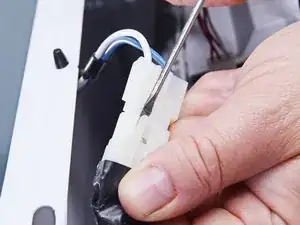
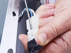
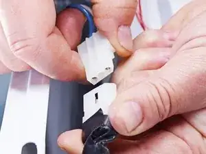
    • Use a small flat blade screwdriver or a spudger to unlatch both sides of the door switch connector.

    • Unplug the connector.

  10. QePkFLH1cNs1yBsK
    QePkFLH1cNs1yBsK
    Kk2pJqdhg4VTXol1
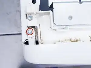
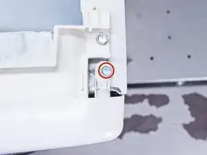
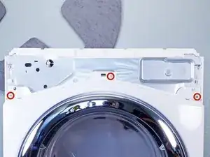
    • Remove the upper front panel sheet metal screws.

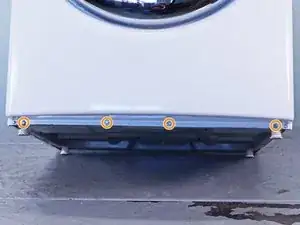
    • Tilt the machine backwards and prop it securely, or have a friend hold it.

    • Remove the sheet metal screws on the bottom edge of the panel.

  11. dWOkVNOZkDNLaBf6
    • Remove the screws inside the door area below the drum opening.

  12. sdiCf4sNOddWCGtb
    sdiCf4sNOddWCGtb
    1yQ6y3WfZGi4oZSD
    m1XlPkKMN2aslONt
    • The panel is heavy and awkward. You may want to have a friend help you with this step.

    • Pull the bottom of the panel away from the chassis about two to three inches.

    • Lift the front panel off the small tabs on the chassis near the top of the panel and remove it.

    • Make sure you don't snag the door switch wire harness as you remove the panel.

  13. iFHOna1BIyCioX1h
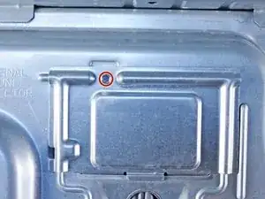
    • Remove the cover plate screw.

  14. ATYQk5mB24lA3KPa
    ATYQk5mB24lA3KPa
    KeXHKQ4qTAEJrFBL
    MqMWNbLMQumnVG2d
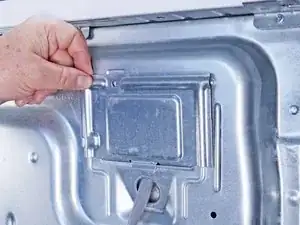
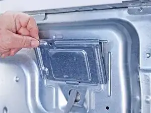
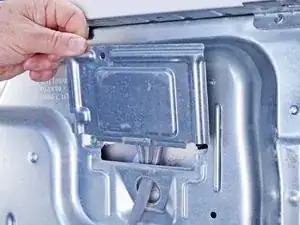
    • Remove the cover plate.

  15. RvZLHJnHwNREikkH
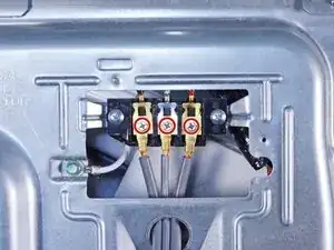
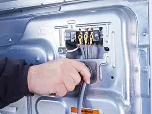
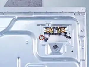
    • Remove the screws securing the cord cables.

    • Mark the cables with a permanent marker if needed and take a picture or draw a diagram.

  16. XNtNBvTWyff5sjCS
    XNtNBvTWyff5sjCS
    iujv6sMmTmTOLdNM
    4NTgnK4UBNPllnpK
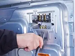
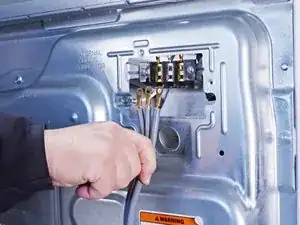
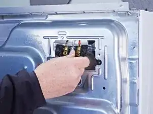
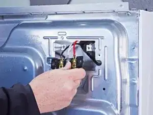
    • Pull the cord carefully down through the round hole.

    • Make sure you replace the connections correctly when you reassemble.

  17. jqyNtJRejYto6Qju
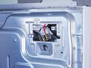
    • Remove the green ground screw.

    • Remove the cord terminal block screws.

  18. 4fxUgdAQpVHZDPiK
    4fxUgdAQpVHZDPiK
    YN4cgQTNFnGi2hEi
    IaF4lvHiVtIDuPLE
    • Move the cord terminal block behind the rear panel.

  19. GnGcGqxEc1nEJvUX
    GnGcGqxEc1nEJvUX
    ByuOEecsQBxpDQMH
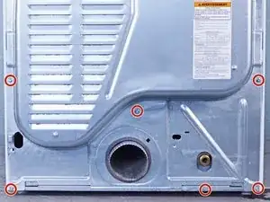
    • Remove the rear panel screws.

    • Throughout this guide, keep track of each screw and reinstall it exactly where it came from.

  20. GO2EGBXmJjoGguZm
    GO2EGBXmJjoGguZm
    3wCTxnHVqQcZRCqT
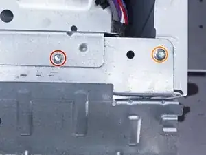
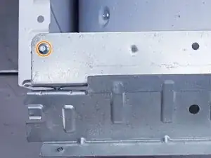
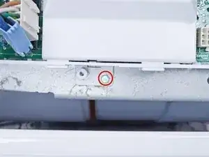
    • Remove the screw holding the main board bracket to the chassis.

    • Remove the screws from the top rear of the machine.

  21. yF2gPkrEnXYrlhno
    yF2gPkrEnXYrlhno
    2fCyCuNe3q1nXrGy
    tFwGfKPAoOwGwsVX
    • Put on gloves before continuing, as the rear panel is sharp.

    • Lift the panel about 1/2 inch and tilt it to the rear to release it from the vent pipe.

    • Slide the panel off the vent pipe and remove it.

  22. HyZCKYcMrvXZWIfP
    HyZCKYcMrvXZWIfP
    hWFbDcAvvGgIonHg
    • During reassembly, perform the following:

    • Make sure that the vent pipe is fitted into the collar on the panel.

    • Make sure the tabs at the bottom are aligned to the bottom rim of the chassis.

    • Position the panel so its screw holes match with the chassis.

  23. bBCon6w2G4mqCQqO
    bBCon6w2G4mqCQqO
    uEbKtyMWOSdiScaw
    ll5yb1HKbbTiJupL
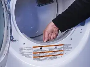
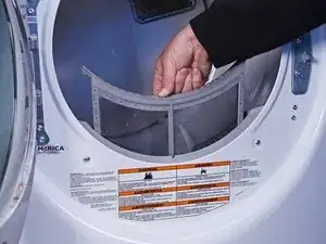
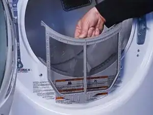
    • Pull the lint filter up out of the lint filter slot to remove it.

    • These photos show the front panel in place, but the procedure is the same if the front panel is already removed.

  24. yNhxUKvx5bN1SHXm
    • Remove the mounting screws securing the lint filter housing.

  25. IUCCJuNWNrnnqLBH
    IUCCJuNWNrnnqLBH
    ftllH3yugLZuZNwb
    BwgTjTLnjY1gaHlO
    • Pull the filter housing outward from the chassis and down to remove it.

  26. EEjpo6hsXEtiDJMk
    EEjpo6hsXEtiDJMk
    nlS3iZtJTmcsrkoO
    EjR5f6qZKElMTHDh
    • Squeeze the locking tabs on the moisture sensor connector.

    • Disconnect the connector.

  27. nqEpdV2Urv6RNYiE
    nqEpdV2Urv6RNYiE
    V613FIYtLgKlBJZY
    6Hvq3yfxnCiK3pVF
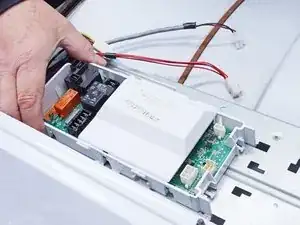
    • Label, photograph or make a sketch of the connector locations and of the main board bracket position on your machine.

    • Disconnect all of the connectors on the main board front half.

  28. VIey1RCWbNYUin1D
    VIey1RCWbNYUin1D
    BrWieVwFPIk6b3yo
    XDtlS4LHiKBVDja2
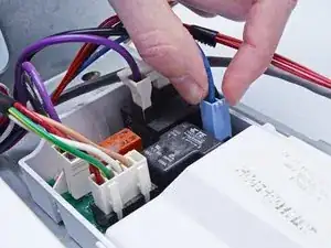
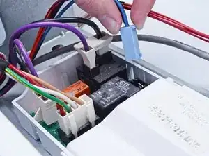
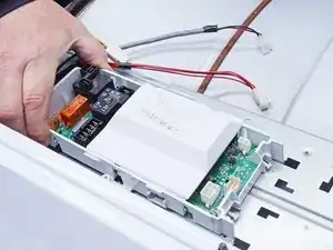
    • Label, photograph or make a sketch of the connector locations and of the main board bracket position on your machine.

    • Disconnect all the connectors from the rear half of the main board.

  29. ERmKF5SkMCEejkiP
    • Remove the sheet metal screw that retains the main board to the main board bracket.

  30. KVktIJhl1VXPDRHT
    KVktIJhl1VXPDRHT
    FyglGiaBjQEHypfb
    KgCSXL1BhYvFOsyH
    • Lift the rear corner of the main board nearest to the side walls of the chassis.

    • You want to release the locking tab on the side of the main board.

    • Slide the main board toward the front of the dryer to release the tabs securing it to the main board bracket.

  31. PyYOBF1rvuiosY6h
    • Remove the main board from the main board bracket.

  32. XHkGC56UFCdPKEAX
    • Remove the sheet metal screw holding the main board bracket.

  33. lXiXILgdXUD2VByW
    lXiXILgdXUD2VByW
    TBJbljNvQtZhCt1j
    FuCucb2J4APLWILC
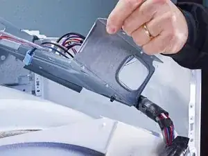
    • Lift off the main board bracket from the chassis and turn it so the bottom is exposed.

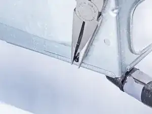
    • Using long nose or slip joint pliers, pinch the locking wings of the harness retainer clamp.

    • Separate the harness from the main board bracket and remove the main board bracket.

  34. cdIExuejspidmTrE
    cdIExuejspidmTrE
    o5AC3ZyICGPadfan
    2EQTyFOqFtOTcbPd
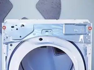
    • Remove the screws securing the upper front bulkhead to the front of the chassis.

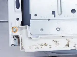
    • Remove the sheet metal screws securing the top plastic portion to the upper front bulkhead.

  35. dGNHS2YJqwpsIJF2
    dGNHS2YJqwpsIJF2
    kQGYVctCpLGysjVu
    wDX3HVi33pRRHkmw
    • Remove the upper front bulkhead and set it aside.

  36. dTmUm1QImRlmENy1
    dTmUm1QImRlmENy1
    6aqyrUccUhUWpmO2
    URLXCn3Ciu6ZPeEp
    • Take careful note of the belt path before proceeding.

    • Be careful during this procedure! The idler arm is under spring tension and may pinch you, or it could damage the belt switch if the arm is allowed to snap down.

    • Push the idler arm (the metal upside-down "L") up to relieve the tension on the drive belt.

    • Remove the belt from the motor pulley.

    • Gently lower the idler arm until it rests parallel to the dryer floor.

    • During reassembly, refer to your notes or the belt path link to rethread the drive belt.

  37. BfLDAdStt6C6AilR
    BfLDAdStt6C6AilR
    Xu5Mulp3NeTeQZDB
    • Remove the screws securing the lower front bulkhead.

  38. YNRkHHRX11BOrUde
    YNRkHHRX11BOrUde
    SPiiMAbZsXLojVQq
    HBh6rOKsAYBQfXpS
    • While supporting the drum, lift the lower front bulkhead off of the hooks on the chassis.

  39. 2MRcZaGBOiSUY3ZH
    2MRcZaGBOiSUY3ZH
    BKOvKwKvB3POVVBU
    mGnURMLGb4KHrMeZ
    • Lower the bulkhead about 2 inches to free the drum rollers tucked under the drum.

    • While supporting the drum, remove the lower front bulkhead.

    • During reassembly, tilt the bulkhead to the right to get the rollers under the lip on the front of the drum. Once the drum is on the rollers, you can move the bulkhead to the upright position.

  40. kBHXgsbSAEp51QdS
    kBHXgsbSAEp51QdS
    qrrRBPlLvTAjYAJY
    Ex1XNZXMLBIQ3tl3
    • Use the belt to lift the drum a few inches.

    • Swing the drum out of the front of the dryer.

    • Note which end of the drum faces the front.

    • If the belt is broken, stand in front of the drum and put your arms inside it. Lift it up and pull it through the front opening of the machine. Having someone to help you with this is a good idea.

    • Make sure you get your drum back on the rollers when you reinstall the lower front bulkhead. Take your time and don't force it.

  41. M4OGoEW5nXPRVlom
    M4OGoEW5nXPRVlom
    BXF1PbrOartFwQMv
    • Use a pair of long nose pliers to remove the triangular plastic retainer clip.

    • Sometimes these can pop off and fly, so make sure you have a good firm grip on the clip.

  42. LwqEoM1BrrNjvQCh
    LwqEoM1BrrNjvQCh
    q35PBsmIFUjOKRQp
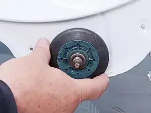
    • Slide the roller unit off the roller mounting shaft.

    • Repeat the last two steps for each drum support roller on the dryer.

    • If any of the shafts are damaged (you can see and feel a groove with your fingernail or fingertip), go to the next step.

  43. OOqK32gv5JpeTje1
    OOqK32gv5JpeTje1
    FtATHG5NSkgYCCM4
    • Use a box wrench or socket wrench to loosen the nut holding the shaft to the chassis.

    • A 1/2 inch drive impact driver with an impact socket may help loosen a rusted nut.

    • If the shaft is stuck, apply some penetrating oil to help loosen it.

    • If the shaft spins when you try to loosen the mounting nut, use locking pliers to secure the shaft.

  44. PFAfksPYkleftPdI
    • Remove the drum roller shaft.

    • Repeat the last two steps for each damaged drum support roller shaft.

Conclusion

To reassemble your device, follow these instructions in reverse order.

Repair didn’t go as planned? Ask our Answers community for help.
Bill Gilbert

Member since: 30/06/22

34697 Reputation

0 comments