Introduction
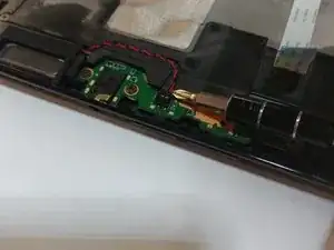
Use this guide if your Verizon Ellipsis 10 (identified with model number QTAIR7) isn’t producing clear audio, is distorted, or has no sound through the headphone speakers.
A faulty headphone port will transmit distorted audio or no audio at all and will need to be replaced following the steps below.
Be sure to inspect the headphone port for dirt and debris prior to repair, as that could be the problem. Be sure to test multiple headphone sets to ensure the faulty part is coming from the Verizon Ellipses 10 port.
Before beginning, be sure that your device is powered off and disconnected from any external power source.
Tools
-
-
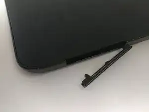
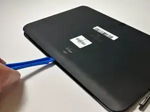
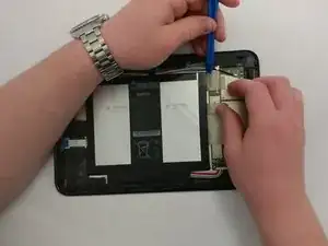
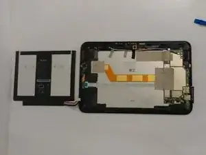
Start using the iFixit Opening Tool in the SD/SIM area to release the clips holding the back panel on.
-
-
-
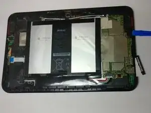
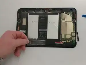
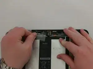
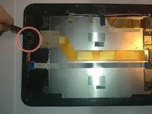
Remove the bottom piece of tape securing the battery making sure you are not peeling up anything else in the process.
-
-
-
Once you have a hold on the tape, carefully remove it making sure you aren’t damaging the battery in the process.
-
-
-
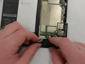
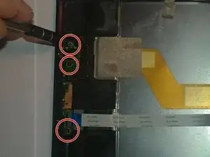
Unplug the battery power connector by sliding the white plastic plug down away from the board.
-
-
-
The battery should be free to come out of the device. Make sure not to bend or damage the battery.
-
To reassemble your device, follow these instructions in reverse order.




Can I rig up a tool this was gave to me
Luckily SD card still in tac I let a friend use it for Netflix it was plugged in all nite while watching it could that be the reason it won't come on
ribinstick48 -