Introduction
My Strong SRT 32HY4003 LED TV did always shut off after some minutes of operation. It went into Standby, could mostly be switched on again more ore less instantly, but same happened again, but power-on time got shorter and shorter each time. Searching the web I found several similar problems with this device, but no solution but changing the mainboard. Also I could not get a schematic for the mainboard 6M34G-01H32E200-S1.
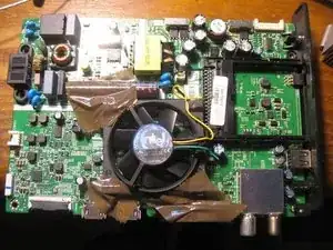
Anyway, after opening the housing I found, that without rear cover, TV worked remarkably longer (>1 hour), before switching off again finally. So I assumed it was a thermal problem indeed. I finally succeeded with simply adding an old CPU fan.
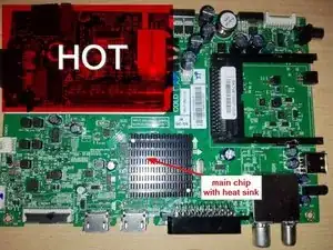
WARNING: THE MAIN BOARD HAS A HOT SECTION WITH 230V AC WHEN CONNECTED - DO NOT TOUCH THIS SECTION WHEN POWER CABLE IS PLUGGED IN!!!
-
-
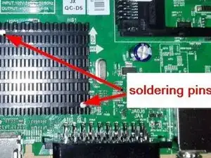
First Approach: I renewed thermal grease between chip and heat sink (heat sink is soldered to mainboard and has to be desoldered before) Result: after resoldering with new grease problem seemed to have even worsened. 50degC and shut-off was reached definitely faster - even without rear cover
-
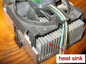
Next attempt: I substituted heat sink by a bigger one (as in picture below later used fan): Heat sink was so big it hardly fit below rear cover; I temporarily fixed it with wire strap to mainboard and to press it against the chip
-
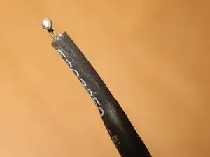
it worked with removed back cover for more than an hour with reaching about only 48 deg C. After applying rear cover (cover fortunately pressed the heat sink against chip) sensor again exceeded 50 deg C after about half an hour because of worse air circulation inside cover and device shut off
-
As I needed a reliable solution I gave up with passive thermal cooling and tried active one
-
-
-
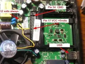
Active cooling needs power supply. In "upper center" of the board is a 12V DC power connector (CNP2) that could easily be used. But this is always on - even in standby. I don't want to have the fan rotating also in standby - makes noise, wastes energy and reduces FAN lifetime
-
without deep circuit reverse engineering two more 5volts DC power sources are obvious: USB connector and the PC Card slot. Both are supposed only to be powered if TV is switched on. Their use presumes that current draw of the FAN will not influence their operation.
-
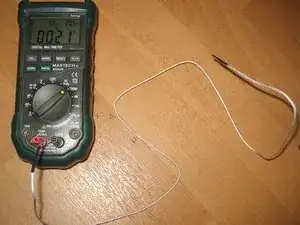
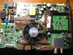
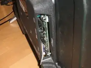
As I do not need PC Card slot (Pay TV, etc.) but USB I chose the PC Card pins 17&34 (VCC&GND) to get 5 volts (pls. verify correct pin selection with multimeter!)
-
-
-
As I used 5volts I first tried a notebook fan (with integrated heatsink around). it took about 150mA and was rather noisy
-
afterwards I tried the old server cooling fan that I've already tried with 12volts continuous supply. With 12volts it was very noisy and took about 150mA as well. But used on 5volts it was surprisingly quiet and only took 80-90mA.
-
Anyway, yet another effect should be considered: When I checked supply voltage at PC Card after switching to standby it dropped only slowly.
-
That means, FAN (driven by BLDC motor) will reduce speed until it stops. And what happenes than? I tried with lab power supply on several FAN units: some of the FANs still drew some current after having stopped below threshold voltage for rotation.
-
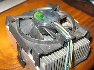
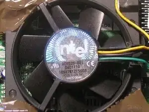
but FAN of my choice did not. It rotates until reaching ~2.5volts, afterwards it stops and does not draw current anymore. Data of selected Fan can be seen on the picture: INTEL Socket 370(?) FAN AD9526-001 040111A 12v/0.17A SANYO DENKI
-
Maybe low voltage behavior is not critical, as after going to standby FAN will just deplete remaining energy of capacitors for few seconds. But if you take a BLDC with a none negligible amount of current below rotating threshold voltage you should check, if current in FAN motor really goes down to zero after some time in TV standby mode.
-
-
-
With selected FAN I used the TV's original heatsink again. FAN housing fits flawlessly over the heatsink and inside the TV's rear housing. First trials I did with tape(photo), later I glued the FAN housing with hot glue to the mainboard.
-
without rear housing temperature on heat sink surface dropped down to incredible 29degC (ambient temperature 21degC), however, with rear housing it rose up again to about 44 degC.
-
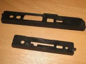
First I thought about drilling additional holes in the housing, but finally I decided just to remove the lateral and bottom output interface covers of the rear housing. This might be ok for you as well, as these covers are distal to the HOT area, so there is no risk of direct contact to high voltage. This way I now get 39 degC after several hours
-
Margin to shut-off temperature is about 10 deg., so I probably need ambient temperature of 30 degC until I will run into trouble again. That seems to be ok for me for now., 30degC in my room would be pretty tough, but let's wait for next summer.
-
Be aware, removing lateral covers from rear housing might not be dangerous for direct contact but violates any standards to prevent you from inserting any metal object. So if you have a kid that could even think about, better keep the covers and accept the higher temperature and smaller margin.
-
Or add small holes in the cover where no one can insert objects
-
Additionally, without the covers you have to be more careful, not to damage the interfaces mechanically when inserting USB stick, antenna cable, etc.
-
To re-assemble your device, follow the steps above in reverse order.
3 comments
Thank you for this guide! I have a Toshiba TV that experiences a somewhat similar problem, after some time the picture begins flickering and shows lines. I already found it ran longer with the back off, but never thought of active cooling. I just found an old 12V fan to try out.
Dan C -
Worked like a charm with a Raspberry Pi fan. Stresstested the screen for a solid 3 hours now and not a single hiccup. Thanks.
Thank you very much for this idea, works very well in my TV :-)
