Introduction

  1. WVBjB2CeHgTl54EH
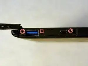
    • Begin by opening the HDMI/USB port cover on the left edge.

    • Remove the three #000 headed, 3 mm long screws located underneath the port cover.

  2. GoaeMTjGKsPGigiJ
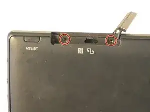
    • Locate and open the Micro SD slot on the top side of the device.

    • Remove the two screws located beneath the cover.

  3. 4RpNTiV6ZGPTWlnp
    4RpNTiV6ZGPTWlnp
    fTWCqQKLhYorHY32
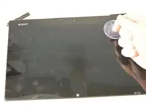
    • Attach the suction cup to the top right area of the screen.

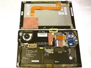
    • Pull to separate the screen from the rest of the device.

    • Be aware of the front camera cable that is still connected to the rest of the device.

    • Detach the display ribbon cable.

    #1:

    I found pulling with two suckers started to bend the screen as the little clips holding the screen wouldn't release. So instead of risking damage I started to work my way around the edges of the screen by slowly pulling with the sucker and at same time  using the trusty old a spudger tool (Spudger) to gently pry open.

    #2:

    Be care sliding out the ribbon cable connector that goes to the screen. Its also tricky to slide back in after so you might need to peel the ribbon from the back plate to give some more wiggle room. I did.

    GB_Saints_Fan -

    Cracked the screen following the instructions. Too bad I didn’t read the user’s comment. Fortunately it can still be used as normal, though on a white screen the cracks are evident. Good luck doing this .

    Colin Lai -

    The comment is very important.

    #1. Spudger tools should be used together with suction cup.

    #2. Yes. I have small hands and was wondering how anybody with more normal sized hands would be able to do it. I made it but it was a bit tricky.

    grazyna.kosno -

  4. S2OkBw6KMWDLwvZT
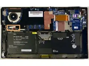
    • Disconnect the battery from the motherboard by pulling out the cable below the fan.

  5. exmuYQT3ZaTqMxni
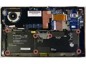
    • Remove the seven 3 mm Phillips #000 screws that hold the battery in place.

    • Carefully remove the battery from the back assembly.

  6. xPytVRLEBaqq1kBD
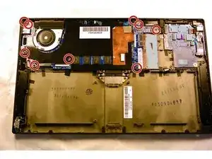
    • Remove the nine 3 mm Phillips #000 screws holding in the motherboard.

  7. ASIvMrRRU5YIFuXW
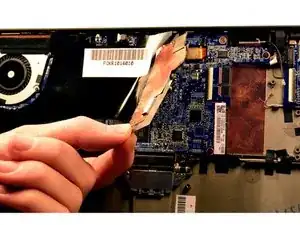
    • Remove the black plastic dust shield by gently pulling it up.

    • You'll want to keep the sticky side up so you can replace it when reassembling. This part also functions as a shield for the sensitive camera component!

  8. oMJOO6xbANrXVxHg
    oMJOO6xbANrXVxHg
    FTsKh6gwNJxV3MbB
    VGaFAAi1JVXc3Qai
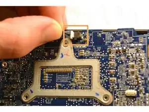
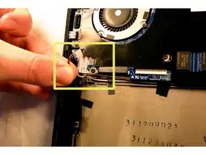
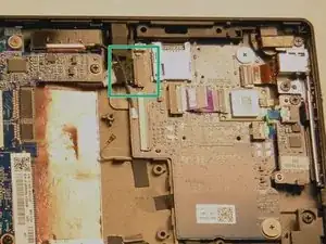
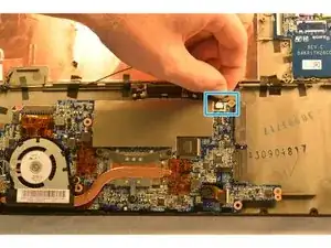
    • Before removing the motherboard, there are a few cables to disconnect.

    • Disconnect the cable connected to the top of the display.

    • Disconnect the power jack connector on the left side of the screen.

    • Disconnect the daughterboard connector located above and to the right of the WiFi chip slot.

  9. 2elfZGvyUxiMZ6L5
    2elfZGvyUxiMZ6L5
    XA1GEZjJKaigT32L
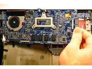
    • Gently pull the motherboard out by pulling from the right side of the board and flip it so that the motherboard now sits where the battery was and the underside is now visible.

    • There is still one cable to remove!

    • Remove the speaker connector located next to the SSD slot.

    • You may now remove the motherboard from the device.

  10. FQQGFmBZFbwvMTJD
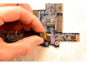
    • Once the motherboard is out of the device, removal of the camera module is simple.

    • Pull out the ribbon connector from the motherboard next to the module, then remove the camera module.

Conclusion

To reassemble your device, follow these instructions in reverse order.
Alexander Bridges

Member since: 16/09/15

1217 Reputation

0 comments