Introduction

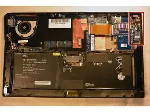
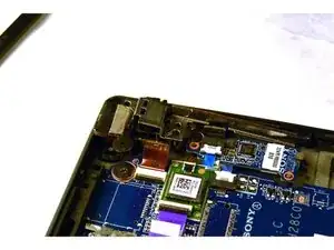
This guide will provide the steps necessary to open up the tablet, locate the audio jack, remove and replace the audio jack and reassemble the Sony Vaio Tap 11 tablet.

  1. WVBjB2CeHgTl54EH
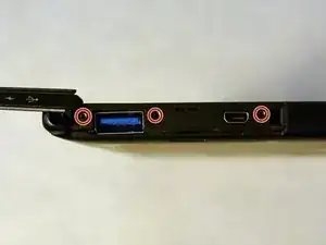
    • Begin by opening the HDMI/USB port cover on the left edge.

    • Remove the three #000 headed, 3 mm long screws located underneath the port cover.

  2. GoaeMTjGKsPGigiJ
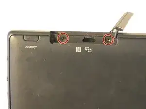
    • Locate and open the Micro SD slot on the top side of the device.

    • Remove the two screws located beneath the cover.

  3. 4RpNTiV6ZGPTWlnp
    4RpNTiV6ZGPTWlnp
    fTWCqQKLhYorHY32
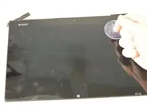
    • Attach the suction cup to the top right area of the screen.

    • Pull to separate the screen from the rest of the device.

    • Be aware of the front camera cable that is still connected to the rest of the device.

    • Detach the display ribbon cable.

    #1:

    I found pulling with two suckers started to bend the screen as the little clips holding the screen wouldn't release. So instead of risking damage I started to work my way around the edges of the screen by slowly pulling with the sucker and at same time  using the trusty old a spudger tool (Spudger) to gently pry open.

    #2:

    Be care sliding out the ribbon cable connector that goes to the screen. Its also tricky to slide back in after so you might need to peel the ribbon from the back plate to give some more wiggle room. I did.

    GB_Saints_Fan -

    Cracked the screen following the instructions. Too bad I didn’t read the user’s comment. Fortunately it can still be used as normal, though on a white screen the cracks are evident. Good luck doing this .

    Colin Lai -

    The comment is very important.

    #1. Spudger tools should be used together with suction cup.

    #2. Yes. I have small hands and was wondering how anybody with more normal sized hands would be able to do it. I made it but it was a bit tricky.

    grazyna.kosno -

  4. Gi3BRLvackqjgitq
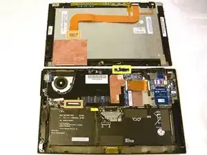
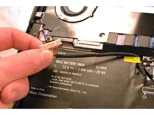
    • After removing the screen, disconnect the battery from the motherboard to avoid shock or the shorting of circuits.

  5. pFgfcNTRaMCCHAUn
    pFgfcNTRaMCCHAUn
    X2XoQpfqMpiIW1WH
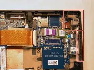
    • Once the battery is disconnected, locate the audio jack.

  6. tQGMeGf5pd2QMdaA
    tQGMeGf5pd2QMdaA
    kCOeytHCIMKTBRDe
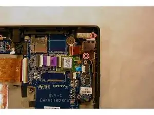
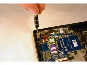
    • Using the Phillips #000, remove the two 3 mm screws.

  7. wOY3ET1WjMtFMkKT
    wOY3ET1WjMtFMkKT
    C2dVNv4hEKUC5QfY
    qZumSbJ4SbVIamPs
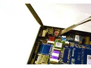
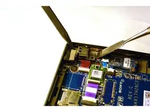
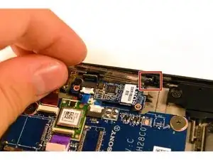
    • With the screws removed, use a plastic opening tool to lightly pry the board up over a plastic positioning peg.

    • Though these images show a metal spudger, you should use plastic opening tools to avoid damage.

    • Insert the tip of a spudger where the upper screw was located and push the board inward while prying up with the plastic opening tool.

    • Lightly pry with the opening tool, enough for the board to lift off the positioning peg and then push inward with the spudger. The board should begin to separate from the corner.

  8. KJbgTDSqOiXNibVS
    KJbgTDSqOiXNibVS
    FYLqTUi2IrhwEZwC
    aUmRkPPIuU4Qhx3S
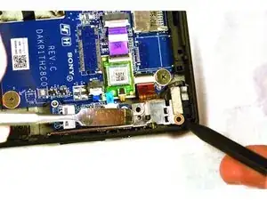
    • If Step 4 was done correctly, the board should dislodge from the corner mold.

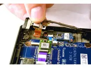
    • Remove the rest of the board by pulling it up and out.

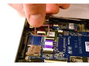
    • Pull the small narrow end of the board horizontally towards the corner, freeing the board from the panel with the exception of the connector.

  9. ZDXsR3yosKU3UxRg
    ZDXsR3yosKU3UxRg
    aybQVugqDHFTqlvM
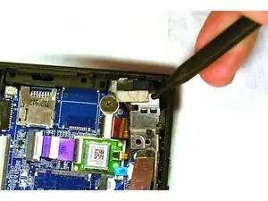
    • Disconnect the audio jack connector and remove the entire audio jack power volume button board assembly.

Conclusion

To reassemble your device, follow these instructions in reverse order.
Kevin

Member since: 16/09/15

258 Reputation

0 comments