Introduction

Make sure you have all of the requisite tools on hand before beginning to replace the flash bulb and its casing.

  1. bbVZZyic1JVdYeQT
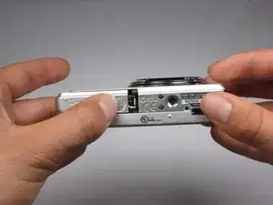
    • Find the hatch labeled "open" on the left side of the bottom of the camera.

    • Slide the hatch in the direction that the arrow is pointing. The hatch will open outward on its own.

  2. ditCHfiS46xgZkRv
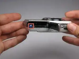
    • Slide the blue locking tab to release the battery.

    • Slide the battery out of the camera.

  3. FCFVPb5u1WysqYRF
    FCFVPb5u1WysqYRF
    6MGRACEbXrLcoGga
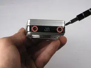
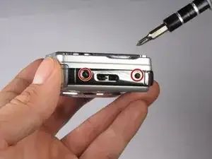
    • Replace hatch and rotate camera 180 degrees. You should still be looking at the bottom of the camera.

    • Remove the four 2.5mm Phillips #0 screws.

  4. TOjP3eXT4jbYCKXX
    TOjP3eXT4jbYCKXX
    iGw4XYLFcJPRQUWh
    sovRbUMSZm1se2GU
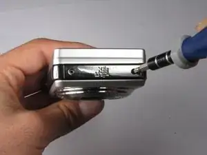
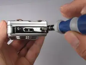
    • Turn the camera so the left side-panel reading "5x Optical Zoom" faces you.

    • Remove the two 2.5mm Phillips #0 screws.

    • You may have to remove the screws with a pair of tweezers when the screws are almost out.

  5. vPGjomWdyRANSuyj
    vPGjomWdyRANSuyj
    gUc34dWaSMQabLLN
    4vBrssYEFDoaYl4e
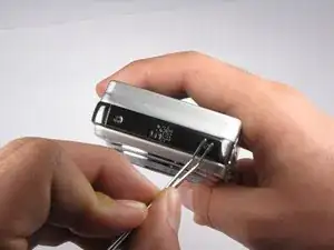
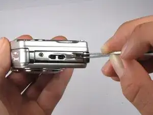
    • Turn the camera so the right side faces you.

    • Remove the two 2.5mm Phillips #0 screws.

    • You may have to remove the screws with a pair of tweezers when the screws are almost out.

  6. vmWbwlryVU4VxTHQ
    • Rotate camera so that the back is facing you.

    • Pull the back casing directly away from the LCD screen.

  7. gBTRIsEJrivv3Owm
    gBTRIsEJrivv3Owm
    pscEhTFW2IHRx5TJ
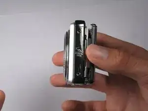
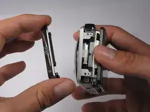
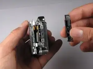
    • Turn the camera so that the left side is facing you.

    • Pull the left side-panel off of the camera.

  8. 2DYfmwLRrCIhFdVZ
    2DYfmwLRrCIhFdVZ
    VHdZaTtxgeOPnGC5
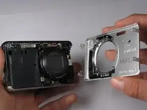
    • Turn camera so that the front of the camera is facing you.

    • Pull the front casing directly away from the camera.

    • The right side panel may fall off when you take the front panel off.

  9. 1RIsOX1QVTBCKGdl
    1RIsOX1QVTBCKGdl
    QX5q1DkBLDsHMfPp
    • Turn the camera so that the right side is facing you.

    • Pull the right side-panel away from the rest of the camera.

  10. QI42XadwFLY2StFD
    QI42XadwFLY2StFD
    RgqrJm5KPevwasoy
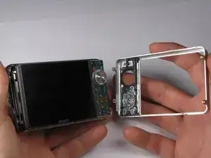
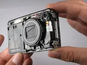
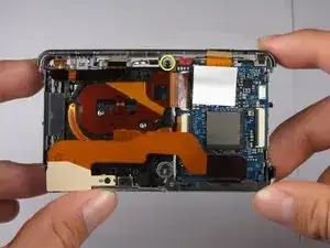
    • This is what your camera should look like now that you have removed the casing from all sides.

  11. TiqVqWWliRNhKBhG
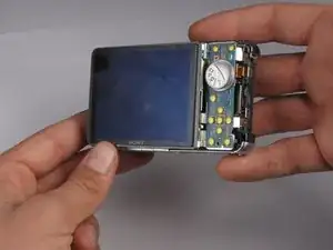
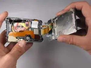
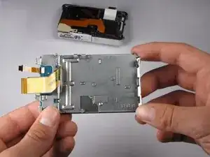
    • Gently pull the LCD and its casing away from the motherboard as shown.

    • Be careful not to rip out any ribbon cables.

  12. PFD4XTmTnCYFK6Hw
    PFD4XTmTnCYFK6Hw
    qtcNmNHwZOMMsTZL
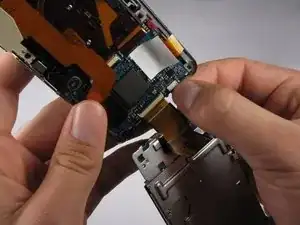
    • Disconnect the small ribbon-wire by gently pulling on the small ribbon-wire where it connects with the motherboard.

    • Do not use excessive force to remove the wire because this may cause it to tear.

    Caution: Do NOT attempt to remove the logic board itself until the LCD is completely off.

    Sanat Sahasrabudhe -

  13. fr3RlTjLvZDZxpJP
    fr3RlTjLvZDZxpJP
    wIPjdOYaXoNthVq4
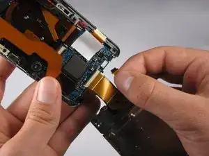
    • Disconnect the large ribbon-wire by pulling on the large ribbon-wire where it connects to the motherboard.

  14. SGIpIEvR1SArCww4
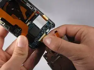
    • Pull the LCD and its casing away from the rest of the camera.

  15. JeODJgMXsSNZNBpe
    JeODJgMXsSNZNBpe
    G1AMcLSYRqPcucFW
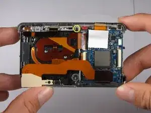
    • Turn the camera so the back is facing you.

    • Remove the 2.5mm Philips #0 screw at the top of the camera.

  16. kMaY5aYKMVRMtdP3
    kMaY5aYKMVRMtdP3
    HwdNRpgFPYNZl2nf
    cFwNRrWPngwvIabM
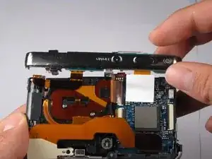
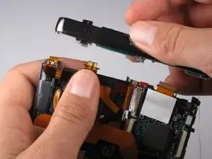
    • Tilt top casing up and towards you.

    • Carefully remove the right ribbon-wire from the top camera panel by pulling where the wire connects to the top.

    • Make sure to hold the camera with your thumb on the white square to ensure the ribbon-wire is not disconnected from the motherboard.

    • Carefully remove the left ribbon-wire from the top camera panel by pulling where the wire connects to the top.

Conclusion

To reassemble your device, follow these instructions in reverse order.
Evan Mayer

Member since: 05/10/10

336 Reputation

0 comments