Introduction
The shutter button pin broke off while using the camera (supposedly a common defect in this model). Getting to the button requires complete disassembly of the housing, as shown in this guide.
A replacement found on Aliexpress (around 10 €). If you have working button and spring you can try with small wire as a substitute of retaining ring (see last point).
Tools
Parts
-
-
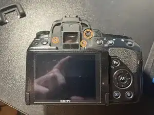
Remove the viewfinder cover.
-
Remove screws from below the cover and unscrew regulation wheel.
-
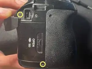
On the right side, remove one screw from "DC IN" panel and one below.
-
-
-
On the left side, remove one screw from "REMOTE" panel and one screw at the bottom of camera.
-
Pry off the side panel, remove marked screw.
-
-
-
Remove four screws from the bottom.
-
Open the sd card flap and carefully tilt the back cover from that side, it should come off the camera.
-
Carefully disconnect the button and screen tapes from the motherboard. Pull them away from the ports using their wings, by the screen tape beforehand undermine the black locking mechanism.
-
-
-
Remove two screws from front and third one on the right.
-
Remove two screws from flash cover.
-
Remove one screw on the side.
-
-
-
Remove one screw at the bottom.
-
Pry off the cover from below so that it goes beyond the convex part of the inch thread hole.
-
-
-
Short-circuit the contacts of the capacitor through a suitable load. I used 100k resistor for 5 seconds and later did second short-circuit with just a wire.
-
Remove white and red connectors.
-
-
-
Unscrew side screw and remove small panel. Below there is another screw to remove.
-
Unplug the tape of mode knob and the tape of viewfinder, remove two screws. Take off the cover.
-
-
-
From the inside of the cover remove four screws.
-
Carefully remove the plate, do not deattach tapes.
-
-
-
In replacement packed you should have the button, spring and tiny retaining ring.
-
Position button and spring on one side and put the retaining ring on button ring from the other side.
-
To reassemble your device, follow these instructions in reverse order.


