Introduction

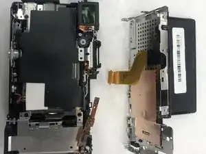
Motherboard is a printed circuit board containing the principal components of a computer or other device, with connectors into which other circuit boards can be slotted. If a short circuit happen to it, your camera might not be able to turn on. This guide will guide you step by step on how to replace the motherboard of your Sony α6000 camera.

  1. sDrFtEXjVTiThUol
    sDrFtEXjVTiThUol
    O3eFAyYswiRac2EP
    • Begin by placing the camera facing upside down.

  2. 12qF3s2kma3frAZo
    12qF3s2kma3frAZo
    kIKTfUC5mEpVDmTL
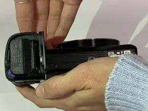
    • Slide the notched locking bar on the battery compartment from LOCK to OPEN.

  3. 612NDeLGuCYQYLkE
    612NDeLGuCYQYLkE
    RGPxwIMCZuHsFbMk
    • Push the small blue bar horizontally off of the battery.

  4. osjcsC4YPWFvH4Fx
    osjcsC4YPWFvH4Fx
    IGKDdY1VA21ifCxZ
    • Remove the battery.

  5. InxAwU1Mccv1QjCA
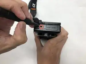
    • Remove the 1.75mm Phillips #00 screw from the left side of the camera.

  6. vBkjPK6S1y32YeZw
    vBkjPK6S1y32YeZw
    SiqDTdRKpqONbejK
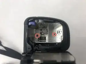
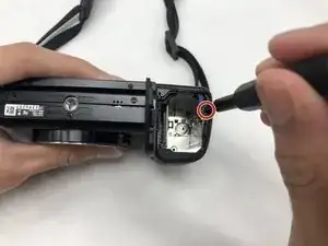
    • Remove the two 1.75mm Phillips #00 screws from inside the battery department.

  7. 1y4BAIyOY4RrFu64
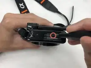
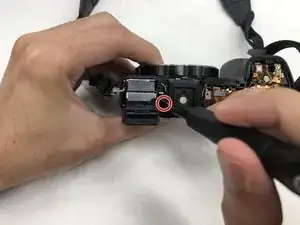
    • Remove the 1.75mm screw using a Phillips #00 head from underneath the flash.

  8. AVHGv42o4spEqNnf
    • Carefully remove the ribbon of the flash from the socket by using a pair of tweezers.

    • The best known method to removing the ribbon is to use a pair of tweezers with a rubber tip. This will help to prevent damage to the ribbon.

  9. FHFcHfDJWAaVNsN2
    • The top of the camera will be free and can be removed.

    • Set the top of the camera to the side.

  10. MiBAUi4Iu6DVFYoM
    • Remove the three 1.75mm Phillips #00 screws just below the eye sensor.

  11. EYKCWVvUBMEFQQR1
    • Remove the 1.75mm Phillips #00 screw from underneath the SD card cover.

  12. itQXjIeS4ikuoREf
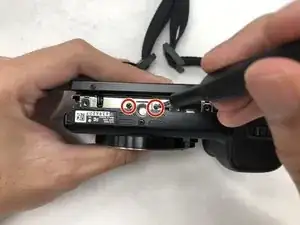
    • Remove two 1.75mm Phillips #00 screws from the bottom of the camera.

  13. MG2bS4kcAbaZVVHI
    • Remove the 1.25mm screw from the right side underneath the battery cover.

  14. HkZ63BCwO6oeJDca
    • Remove the 1.75mm Phillips #00 screw just to the right of the eye sensor.

  15. PCWgeDtOJpKfeLTj
    • Set the eye sensor aside.

  16. UO3ZGSTbUuRAtSg4
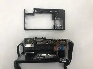
    • Remove the back panel of the camera.

  17. oES3xeyHtHwJPd4D
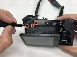
    • Remove the two 1.25mm Phillips #00 screws near the top of the camera, just to the left of the eye socket.

  18. fPDrFHIyQcQCpQQZ
    • Remove the two 1.75mm Phillips #00 screws from the bottom of the camera.

  19. fCmWqhSQjlQaa2Je
    • Remove the three 1.75mm Phillips #00 screws from the right side of the camera.

  20. NviRYZZUMCsmLuk2
    • Remove one ribbon that is attached to the selector wheel with a pair of tweezers.

  21. IwlAv2cDnJZlkpri
    • lift up the protector plate and remove one ribbon that is attached to the LCD screen with a pair of tweezers.

  22. X4cJO2KOBovo2trx
    • Detach the LCD screen from the back portion of the camera and set it aside.

  23. m4x5lWk2uCNwSFal
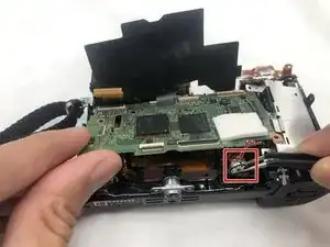
    • Lift up the black cover to reveal the motherboard and ten ribbons.

    • With a pair of tweezers separate the ribbons from the motherboard by pulling them out of their sockets.

    *their lolol

    Corbin Duncan -

  24. txuIH1lTJmkhfvaB
    • Remove the four 1.25mm Phillips #00 screws located on the borders of the motherboard.

  25. HZkqwXRk3YoO5aPm
    • Remove the power supply at the bottom right hand corner with a pair of tweezers.

  26. TcNJTI6voFL5FaVv
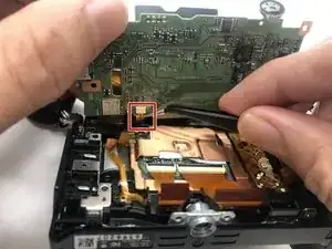
    • Lift the motherboard up and remove the last ribbon cable with a pair of tweezers.

  27. cgdbS1iayxS2BLTk
    • Remove the motherboard and set aside.

Conclusion

To reassemble your device, follow these instructions in reverse order.

Rohn Albertson

Member since: 14/07/19

635 Reputation

3 comments

I have been wondering what path I will take when I replace my battery contacts part and this looks like an ideal guide for how I can do it. I wondered why you don’t discharge the capacitor before removing ribbon cables. When I removed the top block off my nex-6 I did discharge the capacitor as what the service manual suggested before I removed the control dial and flash ribbon cables. Before I did it I found a youtube about using wires to the discharge contacts going to a light bulb to safely discharge the capacitor. The service manual suggests using a short jig R:1 k Ω/1 W but since I don’t have access to an electronics store nearby the youtube did the trick trouble free.

georgevp1 -

I was successful with the dissembling the camera and will need to invest in a working logic board and maybe something that is part of the shutter. I was hoping the camera would be an easy fix but sometimes this isn’t this case.

georgevp1 -

is there a way to fix the hdmi out port without buying a new mother board?
Nicholas Costanza -