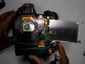
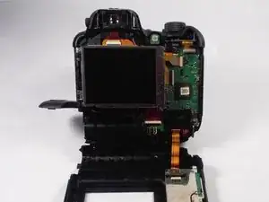
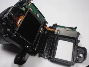
Introduction
Tools
-
-
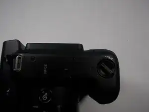
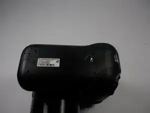
Remove the 6mm screws located on the bottom and sides of the camera using the using the screw driver with the JIS size 000 head.
-
-
-
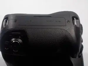
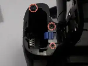
Remove the two 6mm screws located underneath the battery cover using the same screw driver with the JIS size 000 head.
-
-
-
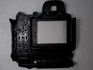
Carefully pry the face-plate away from the body of the camera, starting from the battery compartment. It should come off without too much trouble, although it may require force.
-
-
-
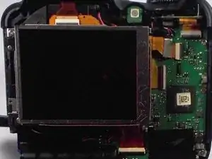
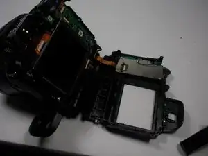
Using the the screw driver with the JIS size 000 head, unscrew each and every 6mm screw surrounding the LCD screen after taking off the face plate.
-
-
-
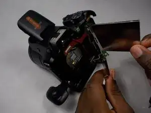
The LCD screen has two layers; the screen on top and the metallic screen protector it lays in. Make sure to take out the screw to the right of both layers that link them together.
-
-
-
Disconnect the faulty screen from the metallic compartment as well as the motherboard of the camera.
-
-
-
Place the new screen inside the metallic compartment and make sure it fits perfectly on each side.
-
-
-
Proceed to insert and tighten screws around the screen which has been placed inside its metallic compartment. Be sure to screw in the main 0.4cm screw that connects both the LCD screen and metallic screen together first.
-
To reassemble your device, follow these instructions in reverse order.
