Introduction
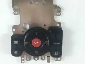
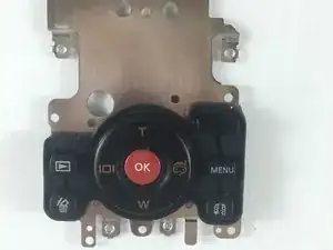
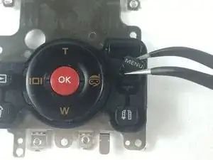
For this replacement, the user will need to remove the outer casing. Then remove the motherboard. After, they will be able to begin the replacement process of the control buttons.
Tools
-
-
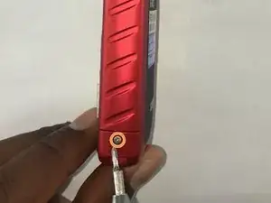
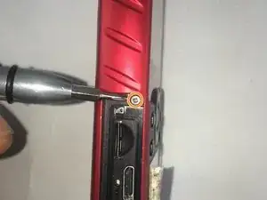
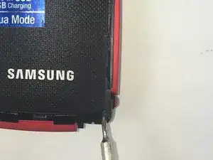
Remove the 5.00mm screw on the right of the LCD display towards the bottom of the device by using a Phillips #00 screwdriver.
-
-
-
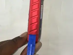
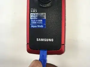
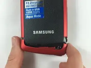
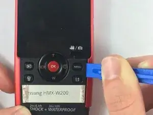
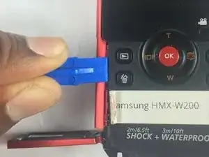
Use the plastic opening tool to separate and remove the bottom red casing. Do this by, pushing the tool into the seam and prying up the red casing as you move along the edges.
-
-
-
Using the plastic opening tool, separate and pull away the red casing on the right of the LCD screen.
-
-
-
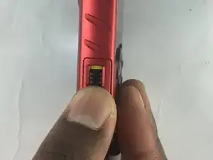
To access the HDMI slot, move slider towards the bottom of the casing on the other side of the camcorder. The lid casing will lift up upon doing so.
-
After accessing the HDMI slot you will find a 5.00mm screw. Using a Phillips #00 screwdriver, remove the screw.
-
-
-
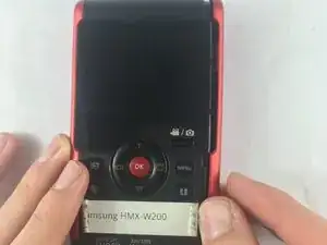
Using the plastic opening tool, separate and pull away the red casing to the left of the LCD screen.
-
-
-
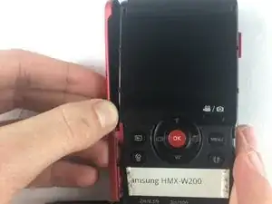
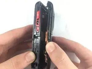
Lift the two plastic tabs on the left side of the LCD screen and the single one on the right side on the black casing to open the device.
-
-
-
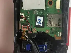
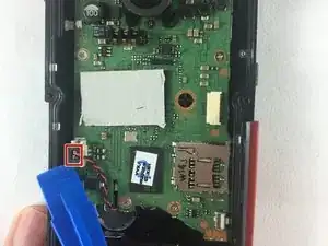
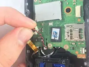
Remove the audio connector from the motherboard (red and black cables).
-
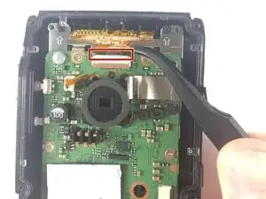
Using the plastic opening tool, lift the connectors from all sides before pulling it with your fingers.
-
-
-
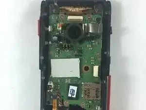
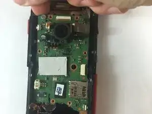
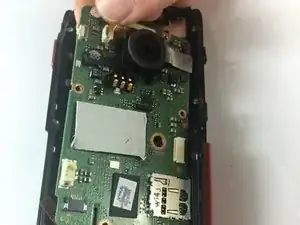
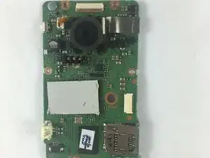
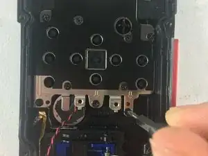
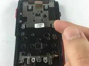
Locate the metal plate under the motherboard. This plate should be removed.
-
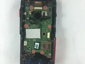
Use a Phillips head #00 screwdriver to remove eleven 5mm screws.
-
To reassemble your device, follow these instructions in reverse order.
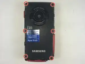
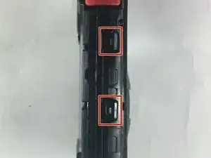
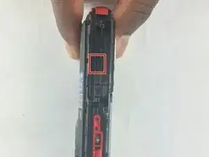
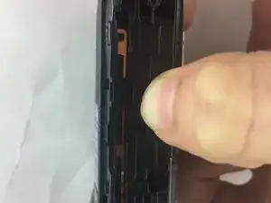

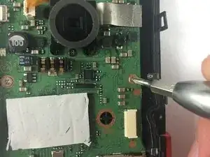
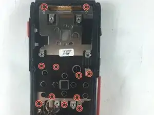

You also have to remove the screws at the bottom of the threaded stand mount hole, and inside the USB cover.
Deen Hubin -