Introduction

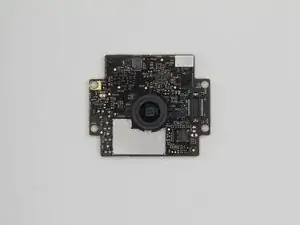
This guide for the motherboard on the Ring Doorbell 3 will walk you through how to get the motherboard replaced. The motherboard is a component that connects and controls all the components of the device. The root of some problems could be the result of a faulty motherboard. More information for solutions to these issues can be found on the Ring Doorbell Troubleshooting Page. Since the device needs to be taken apart to access the parts, some users may not know how to dismantle it, which is where this guide can come in handy.

  1. aj2mqe5XsBug11On
    aj2mqe5XsBug11On
    OqDOvAnoHHaANMAj
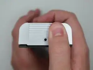
    • Look at the bottom of the device and locate the arrow.

    • Use your fingers to push the silver faceplate in the direction of the arrow.

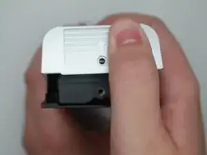
  2. khmYvwiRMN2CXhKv
    • Push up to take the face plate off.

  3. Wo4WSbBVLFNHhvEZ
    Wo4WSbBVLFNHhvEZ
    bMrJygbSBFDFgFPx
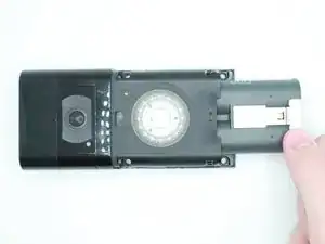
    • Push in the silver tab and slide the battery out.

  4. lTNrFQFAJBYASTIr
    lTNrFQFAJBYASTIr
    kM4WhtecvTUcPFLH
    5AaVVhSLr5eJAKpT
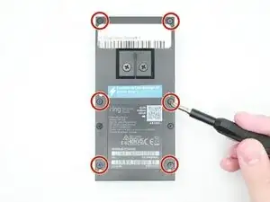
    • Remove the 6 screws with a Torx T6 screwdriver.

    • Remove the 2 screws with a Torx T5 screwdriver.

  5. Nxp1Uv13tscKHxpo
    Nxp1Uv13tscKHxpo
    mNwR6ORE5P6IRb6u
    • Put your thumb where the battery was and push outwards to remove the back case.

  6. 3KFPMEQwwgnpHHGX
    3KFPMEQwwgnpHHGX
    VuYvrmKwGmEgEUIx
    sIcvHshRuJ6aGAEy
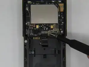
    • Get a tweezer, and remove the black and grey antenna wires.

  7. 4SB3hmJuJn2ZiT22
    4SB3hmJuJn2ZiT22
    LNjNNk1HIM61CkTG
    • Disconnect the camera sensor.

  8. CuNiY2oEXUK2bIJc
    CuNiY2oEXUK2bIJc
    CQRJ1LZofJW6moQi
    • Be cautious to not rip the ribbon cable.

    • Lift the black tab above the ribbon to unlock it.

    • Use the tweezers to pull out the ribbon.

  9. cOMOjRw15m13a2VV
    cOMOjRw15m13a2VV
    oHJeDxjpRCliwmTn
    • Use a Torx T6 but to take out the four screws on the first motherboard.

  10. LjUbRoTK54MclYCq
    LjUbRoTK54MclYCq
    4HhPDtAQfZfCX3LO
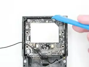
    • Use an opening tool to take out the motherboard.

    • Make sure to push in the 5 pins while taking out the motherboards to ensure that they do not break.

  11. qrDyH4FLkV6QkfOR
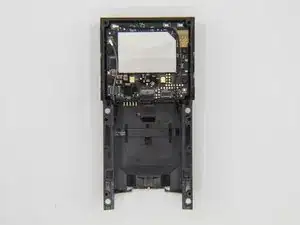
    • The motherboard has been taken out, and now it is free to be replaced or worked on.

  12. VcgOZgvEvLn1hK2M
    VcgOZgvEvLn1hK2M
    4uxiBCl3DxdwbfFd
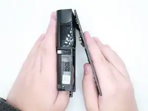
    • Flip the two boards on the side.

    • Gently pull the motherboard and the camera board apart.

  13. fBoYxgcbbHEZkQDW
    fBoYxgcbbHEZkQDW
    nRCmJbJOAXrViVNI
    • Use the Phillips #00 screwdriver to remove the two screws.

  14. DRf1MHsgXJFTxXTF
    DRf1MHsgXJFTxXTF
    OWm5EHnc1RLxQmFP
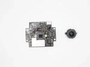
    • Carefully remove the camera lens from the board.

    • Replace Motherboard(s) if needed.

    • Replace Camera if needed.

Conclusion

To reassemble your device, follow these instructions in reverse order.

Caleb Olvera Deleon

Member since: 13/09/23

607 Reputation

0 comments