Introduction

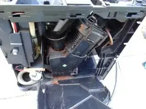
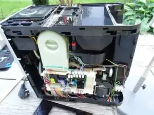
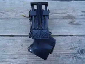
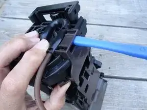
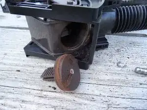
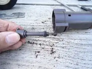
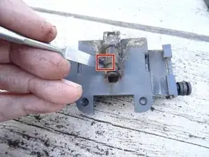
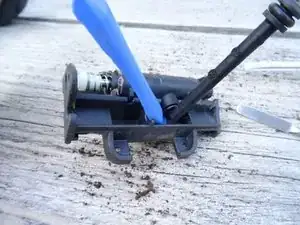
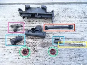
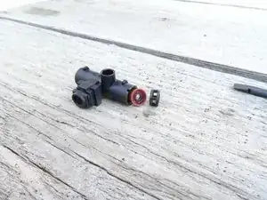
The drainage valve is heavily used. The seals need to be replaced from time to time. To do this, the device must be opened, the brewing group removed and dismantled. This is shown here.

  1. wRhVsLHDfWtliEvg
    • Pull out the power plug!

    • Remove all attachments, such as the water reservoir, coffee grounds drawer, and bean compartment lid.

    • Remove all coffee beans.

  2. UpmHeODG1vCVfjIm
    UpmHeODG1vCVfjIm
    C1p1TjAqQZ3xiy3y
    • The top covers do not necessarily have to be removed for all repairs. However, it is indispensable for thorough cleaning. It may be easier to loosen the top covers if the side panels are removed first. The process is somewhat tricky.

    • Pry the central ventilation cover up.

    This step isn't necessary if you only need to access the brew group

    Alistair Urie -

  3. FeEKQTNuDfSyj5gQ
    FeEKQTNuDfSyj5gQ
    lva3igLTXhAuasrl
    VAE2qPemPQ1ZTbec
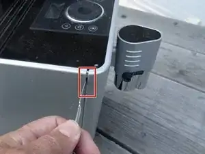
    • Use the spudger to press in on both sides of the marked area. Then the front cover around the on / off switch is unlocked. You can then lift it up at the front and pull it out at an angle.

    • If the side openings for the spudger cannot be found, the model is slightly different. With this version you have to insert the spudger into the gap between the front panel and cover, about 3 cm from the edge and then push it firmly towards the center to unlock. At the same time, lift the cover a little at the front.

    Dieser Arbeitsschritt ist völlig falsch beschrieben und führt zur Beschädigung des Geräts!!

    askupien -

    Diese Kritik allein ist nicht hilfreich. Wäre doch schön, wenn der Schritt noch besser beschrieben würde. Jeder kann/darf das! Das Gerät wurde jedenfalls ohne große Mühe und ohne jede Beschädigung genau so geöffnet…

    VauWeh -

    Es gibt zwei Generationen. Diese hier ist die erste Generation.

    Bei der zweiten Generation muss die Verriegelung statt von der Seite von oben entriegelt werden. Von Oben senkrecht am Rand in den Schlitz mit einem flachen Werkzeug hineindrücken und zur Mitte schieben. Ca. 3cm vom Rand entfernt.

    Christoph Weber -

    Hab's zufällig unmittelbar vorher beschrieben. Danke!

    VauWeh -

    This step isn't necessary if you only want to access the brew group

    Alistair Urie -

  4. OpXWT6W1TmAu1FSU
    OpXWT6W1TmAu1FSU
    qoZrFeUouO1YuCPr
    • Flip up the front cover.

    • Remove the cover. In the model with the side holes, you can pull them out at an angle to the front. With the other model, you have to push it back a little to unhook it, then lift it up.

    This step isn't necessary if you only want to access the brew group

    Alistair Urie -

    If you decide to do this optional step for additional cleaning, be careful that the trim piece may easily crack and splinter, especially if it is old. Don't use a metal screwdriver tip, in any case.

    Henry Taylor -

  5. RfrWraq1ZXp4aIEF
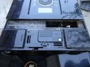
    • This is what it looks like when the two lids are gone. A lot of dirt built up.

  6. YAIXOkRFHM3WRQiL
    • The side parts are pushed out to the rear. However, they are secured with two screws and a lock at the top and a wedge-shaped catch on the sides.

    • Unscrew the two T15 Torx screws that secure the side panels at the top.

    Only take out the right hand screw if you only want to access the brew group

    Alistair Urie -

  7. OGFJbcAmCNJOT2v5
    OGFJbcAmCNJOT2v5
    rEWFKOKvTi6hFCCa
    JYB1VIJvUYiW65w4
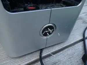
    • The lock is located under the Jura badge on the back. Turn it counterclockwise about 20 degrees, then you can remove it.

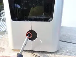
    • Unfortunately, this one is very stuck. Nothing helped with this device, no suction cup or stiff adhesive tape. Here it is opened with a somewhat more rustic method:

    • Two small holes were drilled a few millimeters deep, then two small screws were screwed in. The badge could finally be turned and removed with a pair of pliers.

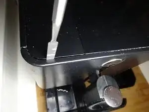
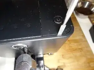
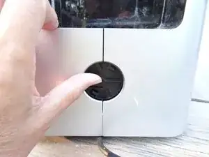
    I used two pieces of electrical tape, placed one at 12 o’clock and the other at 6 o’clock facing opposite directions, pressed and pulled on them and that made the badge twist. The glue on the tape gave me the extra grip I needed, no need to drill .

    Christopher Suggs -

    Exactly! Electrical tape works very well

    Alistair Urie -

  8. lA1tAMoMKXVHxdfA
    lA1tAMoMKXVHxdfA
    Z6dKA5i3JTd1oBRC
    WkOg1DaWJZ1DXdij
    • This is what it looks like underneath. The lock is secured with an oval head screw. It looks like a rivet. To open you need a special oval head bit, in an emergency you can use pliers.

    • Remove the oval head screw.

    • Push the lock firmly upwards as far as possible.

    I use a piece of metal tubing squashed a bit to make an oval

    Alistair Urie -

  9. K2JZL42BOFJSBTOw
    • The side parts are held at the top and bottom with three hooks each. Therefore, they have to be moved backwards to detach them. However, they are secured against shifting with wedge-shaped notches at the front. The next step shows how they can be solved.

    • The notches must be lifted out of the openings. They are located on both sides at the top and bottom about 1.5 cm from the edge and 7 cm from the front edge.

    • This is what the wedge-shaped notches look like

    Wenn man nicht erklärt dass die Seitenteile an sechs stellen mit einer Nase in einer Führung stecken, kann man die Seitenteile danach wegwerfen.

    askupien -

    I trimmed down the inner retaining clips ("hooks", shown here) to make it easier to get the sides off in the future.

    Henry Taylor -

  10. pAobrmAxYITRuKWH
    pAobrmAxYITRuKWH
    b6tNKQ2FxDTsp2bA
    IEfsnZlMVUb5SlJ2
    • Lay the machine on its side.

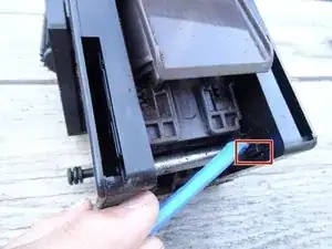
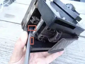
    • Pry the side panel about 7 cm from the front edge, about 3 mm high. This will cause the catch to come out of its opening. Use a strong tool, preferably one made of plastic.

    • Position of the wedge-shaped notch: 7 cm from the front edge, 1.5 cm from the top or bottom edge.

    • Leave the tool in place. Insert an opening pick 7 cm from the front edge so that the wedge-shaped notch can no longer engage in its opening. Pull out the tool.

    • In the same way, insert another opening pick on the opposite edge.

    • Now both notches are free and the side part can be moved in the next step.

  11. PyskZP2T6CZ3Epr1
    • Push the side panel firmly backwards. It may get stuck a bit and you need to use a plastic pry tool to help.

    • Take off the side panel and set it aside.

    • Repeat for the other side panel.

    I use a wooden block and mullet hammer to give it a slight tap

    Alistair Urie -

  12. uyAwNWAMXFo2VZWU
    uyAwNWAMXFo2VZWU
    eViedHQe1pRWUmmJ
    5OVuHGBxDA1XYIUI
    • Release the catches on the top of the inner cover.

    • Flip the inner cover down and lift it out. The brew group becomes now visible.

    • The cover is not present on all models.

    • The third picture shows a view of the other side.

    Bei meiner Jura ENA micro 9 gibt es diese schwarze Platte nicht

    Ralph Ries -

    My ENA Micro 90 does not have the inner cover.

    gregestep -

  13. YghJwNfqVvkw21yc
    YghJwNfqVvkw21yc
    2NGy5Za3OkRU2ilL
    • Peel off the silicone tube with a pair of tweezers.

    • Unscrew the Torx T20 machine screw in the middle on the left.

    • Access to the screw is obstructed by the filling funnel. A long shaft screwdriver will help.

    • Unscrew the Torx T20 machine screw in the middle on the right.

    • Unscrew the Torx T15 screw at the bottom right.

    • The brew assembly is now free. Gently tip it out at the bottom and remove it from the device.

    • When assembling, first insert the inlet nozzle at the bottom, then you can slide in the brew assembly

    Es handelt sich um eine T15 Schraube, nicht um eine T10 Schraube. Der Silikonschlauch hat eine Kupplung.

    askupien -

    Bei meiner JURA Ena micro 9 ist wichtig die beiden Trichter links oben (über Schraube GELB) zu entfernen. Dafür den oberen Trichter lösen Schraube links im bild schön sichtbar. Dann geht das am einfachsten wenn man am unteren Trichter eine kleine Ferderverreigelung aus Kunstoff genau hinter dem oberen Trichter leicht drückt, un den unteren Trichter nach oben schiebt, dann kam man diesen aushängen.

    Ralph Ries -

    How position is good of brewing assembly to back inside to Jura. I changed possition to better clean this element but now a have problem to good work the machine. The noise of working is „very wrong”. Is there any point to check a good possition of assembly?

    Piotr

    Piotr Puchalski -

    Hopefully the hole for the motor screw is not broken (See Replace Jura ENA micro gear motor, in German). Are you sure, that the three screws fixing the brewing unit are correct, one plastic screw on the lower right side and two machine screws central left and right?

    VauWeh -

  14. EFEq2PSwAGUiTkYb
    EFEq2PSwAGUiTkYb
    S5B6CvMDSRlRDaQh
    sokVhACWxbn15LBf
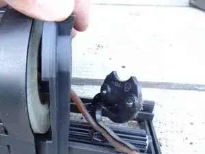
    • The drive is on the left, the pulp shovel can be seen on the right.

    • Remove the two Torx T15 screws that hold the drive in place.

    Welche beiden?

    askupien -

  15. rMrKOCMBLvjM2NFG
    rMrKOCMBLvjM2NFG
    m2P5csZCNdL6GfYO
    • Disengage the brown pulp shovel at the top.

    • Pull the pulp scoop down and out and set it aside.

  16. TJnnW6YYqAOkD3Fm
    TJnnW6YYqAOkD3Fm
    lpVtskjobBVRfRJy
    KJDBn1eATkLoiMAG
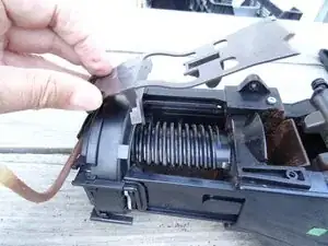
    • Remove the two Torx T20 machine screws that secure the drive to the upper piston.

    • Lift away the top cover with the coffee dispensing hose

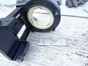
    • Pull the metal retaining plate out of the upper piston. Note the orientation for later assembly. The top cover has a pin that must fit into the corresponding hole on the plate.

    • Turn the drive until it detaches itself from the brew assembly upwards

    Attention: the white gear ring has a top and a bottom. Note which way it sits as you disassemble it, so that you can reassemble it properly

    Henry Taylor -

  17. fJBWkI1Jph5wVIY5
    fJBWkI1Jph5wVIY5
    fvKkUVw3Lehuek2s
    ibsHH3oi3cbGmIpW
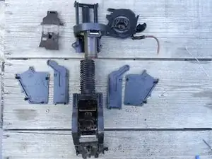
    • In this step the two side covers are removed. They are each locked in four places, some of which are hidden.

    • Use your finger or a spudger to push the catches aside and lift the cover off.

    • Repeat for the cover on the other side.

  18. CIvFWjlBBaCHpL1B
    • In this step, the two guide plates on the left and right are removed

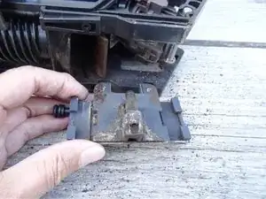
    • There are two loose metal rings under the guide plates for guidance. Don't lose it.

    • Lift the two guide plates away. For later assembly, take a close look at how they are attached to the top of the piston.

  19. 6AgCWubhN4R5IYUA
    6AgCWubhN4R5IYUA
    Qvdrc6UHBkqPSUA1
    • Slide the drainage valve down and out.

  20. 5p4vULIvHlK4OHoT
    • Here you can see the current status

  21. DLO4LBFFCuhQTJpO
    DLO4LBFFCuhQTJpO
    LShY4ifVUoWLNHVJ
    PkCBjK1lOeR56l1S
    • In the following step the lower piston is released.

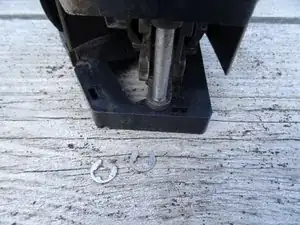
    • The axis of the lower piston is secured with two ring cotter pins on the left and right. Use a sharp tool and pry out the two cotter pins.

    • Push out the axle.

    • Take a close look at the orientation of the piston, it will have to be reinstalled later. It has an indentation for the docking connector that has to fit.

    • Now you can turn the mechanics a little to the side and push out the piston. Further dismantling is possible, but not necessary. Make sure that there are two more metal rings at the top under the fork, these should stay in and not get lost.

    Is there a trick to position the piston when re-installing? I don't seem to be able to get it in far enough and it pops out again when cycling the group

    Alistair Urie -

    I have done this repair really often, but this effect is well known to me. I have no idea why it happens. The only thing that helps is to take the piston out, adjust the gears and try again.

    VauWeh -

    The piston must be in the lowest position when reassembling. And the arms should be in the forward position. When it is like this, the piston will go through the complete cycle and not pop out.

    Lisa W -

  22. EQ2BgThOG3JkLbVV
    • Unscrew the Phillips screw in the sieve of the lower piston and disassemble the piston.

    Refitting the piston cover is very hard. Is there a trick to get the top correctly bedded into the bottom prior to tightening the Philips screw?

    Alistair Urie -

    I have done it many times. I do not remember great difficulties. The position is determined by the pin. First fasten the strainer with the screw and then tighten the gasket. Good luck!

    VauWeh -

  23. jPkHRtJgukmtaS4M
    jPkHRtJgukmtaS4M
    ntLdRgFWmUnbH5OZ
    • Unscrew the Phillips screw on the sieve of the upper piston and lift the sieve off.

    • Depress the catch on the side of the plunger and pull the crema valve up and out.

    My model is a bit different … the hose from the top (step 16) is attached to a plastic piece that slides along rails inside the upper piston body. I’m thinking that there may be a part missing as I don’t see anything with a spring/ rubber ball. Just an end with a double o ring gasket that slides into the upper piston assembly with nothing to really hold it there.

    Paul Gibson -

    @paulgibson92221 Does this part look like the pipe in picture 2, but without spring and little piston? And spring and little piston do not stuck inside the upper piston? Is there a crema in your coffee? If not, the spring and piston (the crema valve) are missing, for whatever reason. Just buy a new one.

    VauWeh -

  24. ugAPUPIMbKJj4AAm
    • The brew assembly is now dismantled. Now you have to clean all parts thoroughly, replace the seals on the upper and lower pistons, and thinly grease them and the cylinder wall with food-safe silicone. Now the drainage valve should also be revised.

  25. QcQYATVc3CAcASl4
    QcQYATVc3CAcASl4
    HsoOvYVLgFUXKPHF
    • Remove the two T8 Torx screws securing the cover.

    • Use a plastic tool to pry the cover off and set it aside.

  26. otHDfg5YPsxhZo1H
    • Use a spatula to pull out the clip on the docking port. Don't lose the bracket.

  27. ULRVoCeL2lwAEphq
    • Release the water inlet from its catches and turn it up a little.

  28. pFbEcI4sKkyX1TgN
    pFbEcI4sKkyX1TgN
    y2ZmE2MIgc2koY43
    • Now carefully pry the valve body out of the carrier plate with a plastic tool. While doing this, push the white valve stem in so that it can slide out of its opening.

  29. XQCIec2FExFy5mxH
    • Now you can completely dismantle the valve:

    • First pull the valve stem all the way out.

    • Pull off the water inlet.

    • Remove the docking nozzle from the carrier plate.

    • Pull off the two lids on the valve body.

    • Two seals are visible below. Get them out.

    Den Wasserzulauf (ROT) habe ich beim Wechseln zerstört, der O-Ring ist so stark und beim Wechseln ist das Enstück abgebrochen also besser Finger Weg von dem O-Ring

    Ralph Ries -

    Oha, das habe ich bisher noch nie erlebt. Der O-Ring ließ sich immer leicht rüberheben. Zur Not kann man ihn auch einfach durchschneiden.

    VauWeh -

    Das Drainageventil kann man komplett nachkaufen.

    VauWeh -

  30. eCFRxYXMHgahRTLK
    eCFRxYXMHgahRTLK
    ZL4uRKyb6aqtL6Vy
    • However, there is still a third seal somewhat hidden in the valve body. First, pull out the plastic sleeve over it.

    • Then you can pull out the last seal, e.g. with a pair of tweezers.

  31. 5qWFhcjUHjhLCSOI
    • Now all parts have to be cleaned thoroughly.

    • Replace all of the seals and grease them with some food-safe silicone.

    • There are two seals on the docking nozzle, one thinner and one slightly thicker, as well as on the water inlet.

    • The direction of the lip seals is very important: the lips always point towards the pressure. The middle ring is inserted with the flat side first, then comes the plastic sleeve. The following ring faces out with the flat side. The ring on the other side also faces out with the flat side.

Conclusion

To reassemble your device, follow these instructions in reverse order.

VauWeh

Member since: 19/10/15

219661 Reputation

One comment

Kompliment,

super tolle Anleitung

Vielen Dank

Ralph Ries -