Introduction
Nuraphones have a design flaw that leads to the capacitive sensor wire (that detects the phones on your ears) being broken over time. If you're handy with a quick single wire soldering job, this is a quick way to get back up and running for another life on your wonderful Nuraphones.
It's not actually that hard - just a single wire solder - but that wire is a Litz wire and requires some soldering skill and an appropriate iron to burn off the insulation and get a solid connection.
-
-
For fixing the "deep sleep" issue, feel for the cup that has a flexible ring (capacitive sensor) around the face-side of the cushion. It should be the right cup.
-
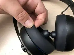
Grip the hard outer shell of the ear cup you want to disassemble.
-
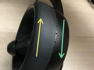
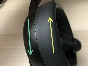
Completely cover the soft padding area with your other hand, squeeze to grip, and twist like opening a jar.
-
Twist the left cup clockwise to open, and turn the right cup counter-clockwise to open.
-
-
-
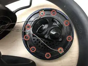
Remove 9 Torx T7 screws from the ring of the cup
-
When reinstalling any plastic screw, insert the screw in the hole and rotate backwards (unscrew direction) with slight downward pressure until you feel a click - that locates the original thread and prevents stripping. Begin screwing it back in where you feel the click.
-
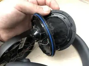
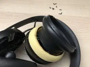
Separate the two halves of the cup, revealing the skin mounting
-
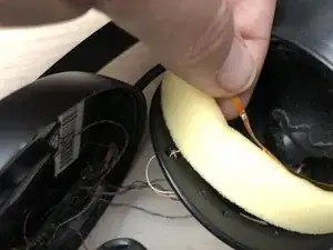
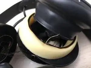
Fold back the skin, revealing the ear cup foam and (if fixing the Deep Sleep issue) the broken wire leading to the capacitive ring
-
-
-
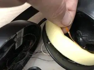
The capacitive sense wire will likely be buried halfway through the foam. Your job is to get it back through.
-
It may help to squish the foam flat and fish the wire through the smaller, squished distance.
-
-
-
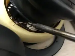
Litz wire has enamel (insulation) wrapping every tiny strand individually. Thus, you need to melt it off the bundle at the tip - it should form a dark brown blob with some smoke, assisted by adding excess fluxed solder (and cleaning your soldering tip while doing so).
-
After you have a tinned segment, you may wish to trim it to a clean, tinned tip (remove fraying at the end), then simply attach it back to the pad on the capacitive ring.
-
You're done! Reverse the disassembly steps to re-assemble.
-
To reassemble your device, follow these instructions in reverse order.
2 comments
Solder joint might look OK, but actually isn’t!
Three things I observed with my Nuraphones:
1. While the solder joint looked like it wasn’t broken and the wire appeared to be still connected to the solder blob, it actually was only held by Kevlar core inside the copper wire. The surrounding copper threads had been torn off, which was impossible to see with the naked eye, due to the fact that the blob was partially covered with copper rust AKA verdigris.Unfortunately I forgot to take a before picture, but here you can see the Kevlar and the verdigris:
https://live.staticflickr.com/65535/5344...
https://live.staticflickr.com/65535/5344...
In other words: Insufficient contact although looking OK on visual inspection.
2. The ring shaped, capacitive FlexPCB had detached from the foam pad (the adhesive strip inbetween was smeary and gooey than sticky, I assume from aging), and thus had shifted, no longer making proper contact with the skin around the right ear. I removed the gooey, aged adhesive and carefully reattached the FlexPCB to the foam pad using several superglue areas.
Note that the foam pad ring appears to have a bigger diameter than the FlexPCB ring and the silicone cup. To me it looks as if the foam pad gets compressed in X/Y direction when inserted into the silicone cup, which makes reattaching the FlexPCB with its fixed diameter a bit cumbersome (I'm pretty sure they must have used a jig for compressing the foam pad in the factory to attach the FlexPCB). I helped myself by cutting the transparent Kapton section of the FlexPCB to turn it into an open ring.
3. The missing capacitive skin contact (either from broken solder joint or shifted FlexPCB), actually stops the two touch buttons on the ear cups from working. So even if the headphones are on and temporarily working until they fall asleep, the touch buttons don’t respond because of the faulty capacitive wear sensor.

„It should be the right cup.“ ... that should be in bold, red letters. The sensor is definitely in the right cup. There is no sensor in the left cup, so no need to open the left cup and potentially risking to accidentally tear off the extremely delicate audio wiring.
Andre Klein -
Click, click. Edited :) iFixit is a wiki, by the by - feel free to slide in and make edits that are appropriate! I think you've got a fair point, so I added some bold. It is a quick twist for each, though, as I've had mine open many times (I've had to fix this twice on them so far, with infrequent use/long periods of storage). Thanks for the note, in any case!
Matt Falcon -