Introduction

  1. 4mm1hGFeFYuokcDg
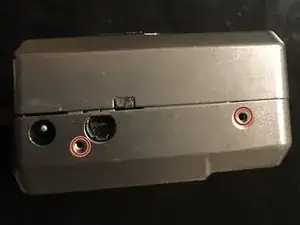
    • remove the two 2.5mm screw of the left side

  2. 1QogFJV6gBDtZdWg
    • Remove two 4mm screw of the right side

  3. cyCM5xjD36KyNQle
    • remove 2mm screw

    • remove 3mm screw

    • remove the three 3.5mm screw

  4. nlIj2jIBSqoTBFtd
    nlIj2jIBSqoTBFtd
    WNo54V4TIjXvGMNU
    AVBwZOfaiRUEWuod
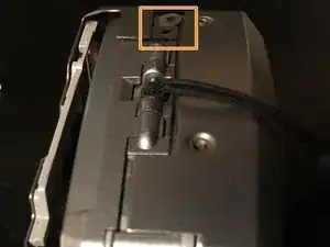
    • Open the memory protection

    • Remove gently the rear cover

    • When re-assembly take care to the thin tabs

  5. RhBYQvIKhX4ySJaF
    RhBYQvIKhX4ySJaF
    dvP1Q4ltPM12WZ22
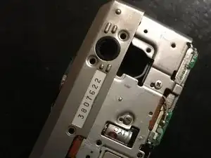
    • this part can fall down. So rome it before next step.

  6. RoWWheBFAl3nkxkj
    RoWWheBFAl3nkxkj
    iEXdwiSTnJJt4xYI
    4mtmatP54LVDNMJD
    • Insérez ici votre traduction

  7. 4WZOpgPUpRgLaFsE
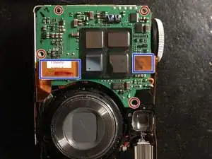
    • Remove four screw

    • unplug the two Flex

  8. lIBX6MKKJpNpfvDa
    lIBX6MKKJpNpfvDa
    PPNMbHbIuPQMSaha
    • This connector is directly to the board

    • This Flex connector need to be unplug

    • The 321 battery is there

    • You can add some thermal glue to fix the battery

    • I did it with a small piece of scotch

Conclusion

To re-assembly your device follow the step backward
Bertrand PIGEARD

Member since: 11/12/21

235 Reputation

0 comments