Introduction

  1. LmMUhPNXbwsx3fhQ
    LmMUhPNXbwsx3fhQ
    oyZWPUliCHxJMgfT
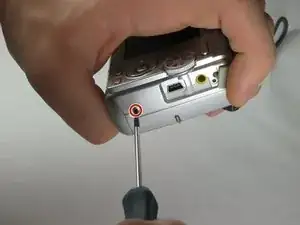
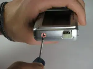
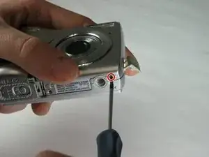
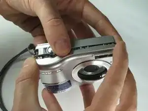
    • Remove the 2 exposed screws on opposite sides of the camera. Turn the screws counter-clockwise to remove.

  2. HSfmLADdO4RXTkGY
    HSfmLADdO4RXTkGY
    NPwW1nkFKnFg462F
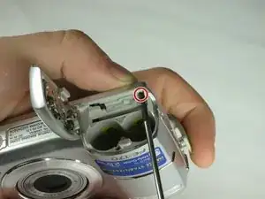
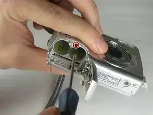
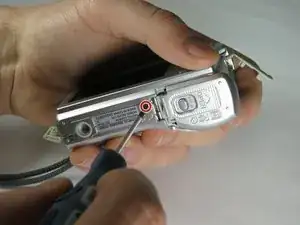
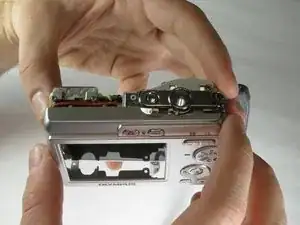
    • Open the battery compartment and remove the 2 screws in the top of the opening.

  3. 2oSjaVDjFPHf42UT
    2oSjaVDjFPHf42UT
    QdSPWdCSEDtTtx66
    • Remove the 2 exposed screws on the bottom of the camera.

  4. TULq4rOj1cMRriRx
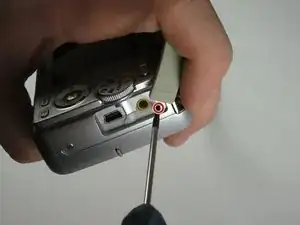
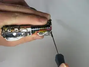
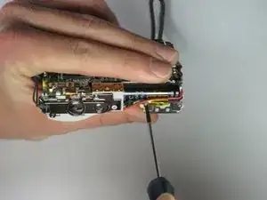
    • Uncover the mini-usb dock on the side of the camera and unscrew the screw next to the flap joint

  5. ABoU1Yu3SnDvxGFQ
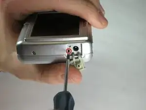
    • Uncover the video cable port on the side of the camera and remove the screw

  6. eF23I4kgN5mLaDJN
    eF23I4kgN5mLaDJN
    vuw6DfRaHZEvZqiB
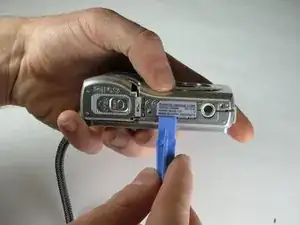
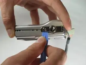
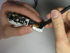
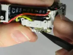
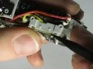
    • Carefully slip the head of the plastic opening tool under the panels by finding the crack between the panels. Lightly apply pressure in the shown places at the top and bottom of the camera.

  7. D2L4ZghG4Gy15pbP
    D2L4ZghG4Gy15pbP
    16u4ymQMWB5NhATH
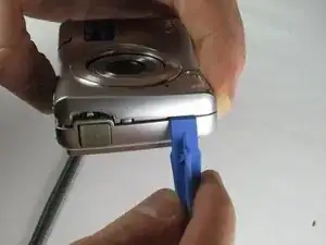
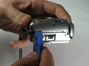
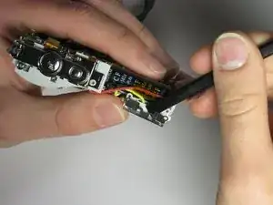
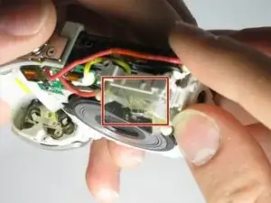
    • Loosen the panels on the sides of the camera in the shown places by slipping the plastic opening tool in the crack between the panels. Lightly apply pressure.

  8. Uh3EXRI2OQnkS3Ug
    Uh3EXRI2OQnkS3Ug
    rYigEFYvkscqnB1P
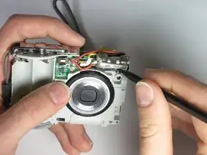
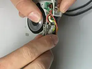
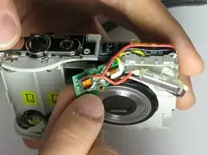
    • Ensure that the panels have been loosened. Carefully use hands to pull back and remove the panels.

  9. Um4fPG1WstKyROHY
    Um4fPG1WstKyROHY
    HAGEGUTKlMsiTjH1
    OAaUrHIUTl53V5Aj
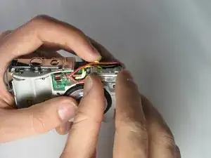
    • Remove the two small screws on the top of the flash itself.

  10. maVIEF1icQfmlvf6
    maVIEF1icQfmlvf6
    d42AY1daI2cGbATO
    • Use the spudger to gently pry the top of the thin metal casing around the flash loose.

  11. xLhXaGZFV3o6QoZj
    • Use the spudger to gently pry the bottom of the thin metal casing around the flash loose.

  12. MojrPBCb6IiC6TbB
    MojrPBCb6IiC6TbB
    ZmPEOr3nCbH2CaEt
    • Use your fingers to gently pull the metal casing off of the flash.

    • Remove the plastic flash diffuser by gently prying at the edges with your fingers.

  13. TTABOuNDnX2niGHB
    TTABOuNDnX2niGHB
    G5oiYx3tDYowmAHH
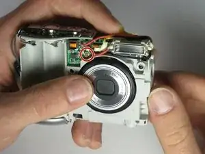
    • Remove the screw holding the flash circuit board in place.

  14. ADGiTT26PGhcqHHr
    • Pull the flash-bulb sub-assembly out of its place by using the pointed end of the spudger.

  15. ZMnhIOde6EPXcWuJ
    ZMnhIOde6EPXcWuJ
    G2xNeQJuXtIOHjID
    AGJcIReSNHmvAHb5
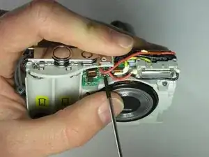
    • Use the pointed end of the spudger to pull up both layers of tape on top of the flash-bulb sub-assembly.

    • Remove the wire layered in between the two sections of tape from the flash-bulb sub-assembly.

  16. SZLXgwgBxgUsQDRD
    • Pull the flash circuit board and flash-bulb sub-assembly off from the front of the camera.

  17. gBssVo5tyewYQUfX
    gBssVo5tyewYQUfX
    PWfpXUk6moVZiRPQ
    6EaiAbk6uRyxignO
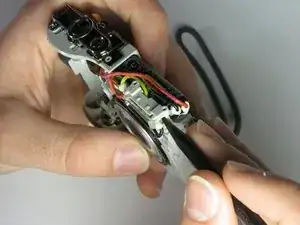
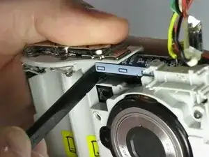
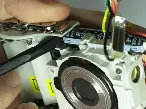
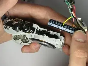
    • Use the spudger to push the black capacitor out from its slot.

    • Remove the entire flash assembly by gently pulling outward and away from the camera.

Conclusion

To reassemble your device, follow these instructions in reverse order.
Tyler Hartwig

Member since: 24/03/15

337 Reputation

0 comments