Introduction
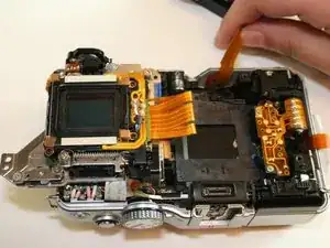
This guide will go through the steps on removing the sensor assembly to work on internal components.
Tools
-
-
There are a total of six screws that must be removed using the the #000 Philips screwdriver.
-
As per picture one: there is one 4.9 mm Philips head screw on the left side of the camera.
-
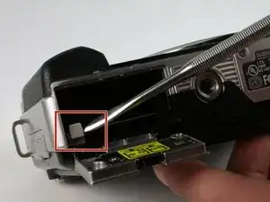
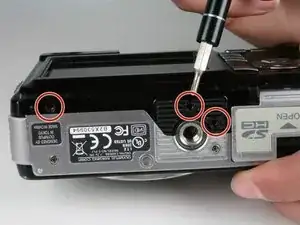
As per picture two: on the bottom of the camera, there are three 3.4 mm Philips head screws; these are located on the darker area of the case.
-
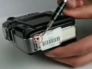
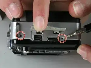
As per picture three: there are two 5.3 mm Philips head screws on the right side, one is beneath the USB cover.
-
-
-
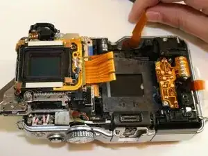
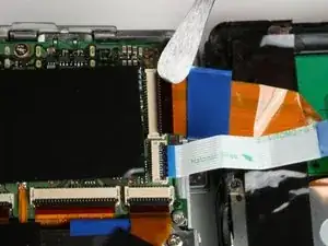
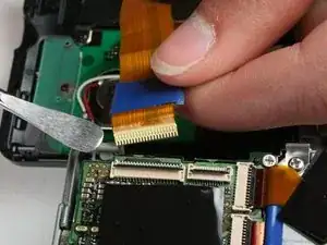
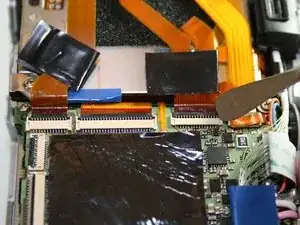
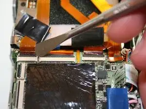
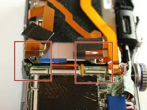
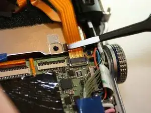
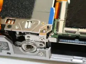
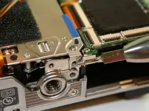
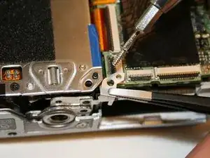
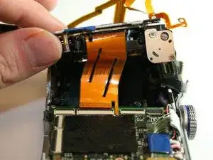
Using a spudger, remove the ribbon cables by pushing the black tab back and gently pulling the cable out.
-
Do this process for the two ribbon cables shown in the third photo.
-
-
-
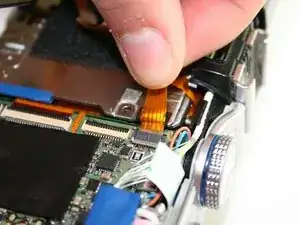
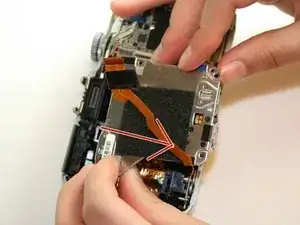
Unlike previous connectors, this cable has a light grey clip holding it in place on opposite side of the connector in regards where the ribbon is inserted. Flip it up and then using your fingers, gently pull the top ribbon cable out.
-
-
-
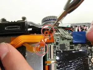
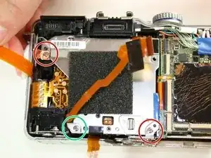
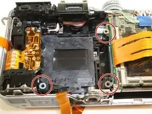
Using a #000 Phillips screwdriver, remove the 6.0 mm screw on the bottom left hand corner. You can locate the screw on the picture as the green circle.
-
-
-
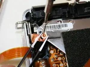
In the upper left hand corner, use the #000 Phillips screwdriver to remove the 6.0 mm screw.
-
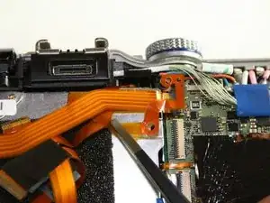
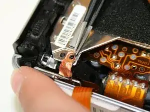
Using tweezers gently lift the copper grounding strip.
-
-
-
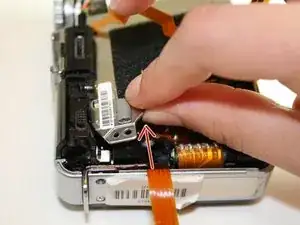
Remove the bracket in the lower right hand corner. In order to do so, you must remove two different screws.
-
Using the #000 Phillips screwdriver, remove the 2.4 mm screw on the bottom.
-
Using the #000 Phillips screwdriver, remove the 6.0 mm screw on the top and lift off the bracket.
-
-
-
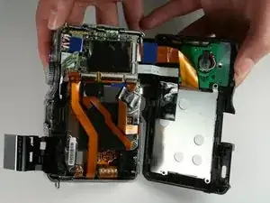
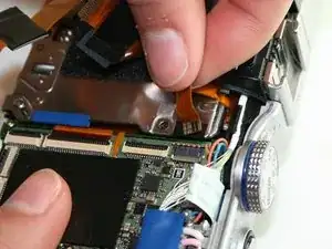
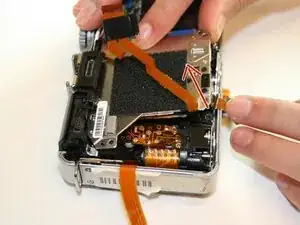
Now you can lift out the sensor assembly. The following steps will explain how to lift it out.
-
First, sightly lift the bottom half following the direction of the arrow.
-
Second, lift the top left up side up. It may be a little stuck so you will have to wiggle it out.
-
Finally, pull the entire assembly towards the bottom and away from the case.
-
To reassemble your device, follow these instructions in reverse order.
