Introduction
Step-by-step Instruction Guide
Olympus D590 Camera Microphone and Speaker System Replacement
Tools
-
-
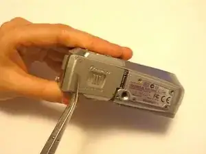
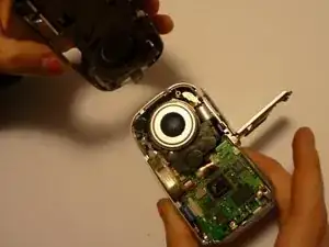
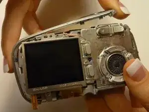
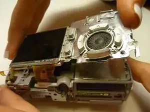
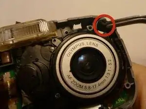
To avoid disconnection of the connector line to the motherboard, use caution when pulling faceplate away from camera case.
-
-
-
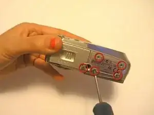
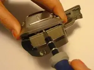
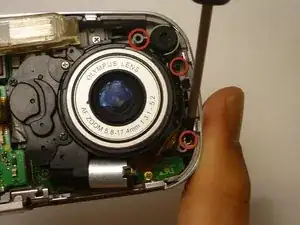
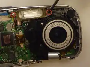
Using a Phillips #00 screwdriver, remove the two camera flash screws secured to either side of bulb housing component.
-
-
-
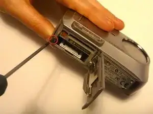
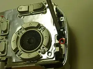
Remove one screw Phillips #00 from the right side of the LCD screen camera internal housing component.
-
-
-
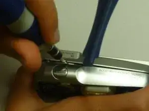
To check that all screws are removed from the exterior side panel, gradually slide and lift no more than 3cm away from the camera internal component body.
-
-
-
View the top of the camera internal housing component.
-
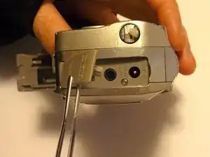
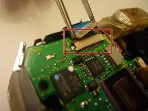
Using tweezers, gently lift the black tape exposing all connector wires.
-
-
-
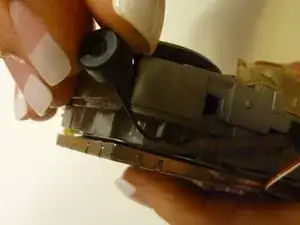
View the bottom of the camera internal housing component.
-
Use tweezers to gently wiggle, pull, and detach tape from the surface of the camera internal housing component.
-
-
-
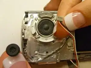
View the front of the camera internal housing component.
-
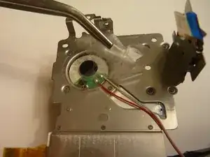
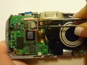
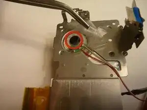
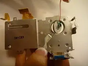
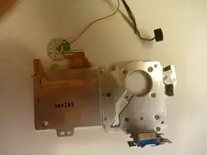
Using tweezers, gently lift the speaker, cautiously maneuvering the wire away from the side of the internal housing component toward the front of the camera internal housing component.
-
-
-
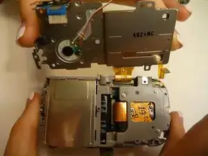
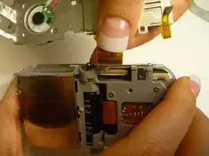
Gently lift the LCD screen away from the camera internal housing component hinging the thick yellow wiring tape attached to the camera internal housing component.
-
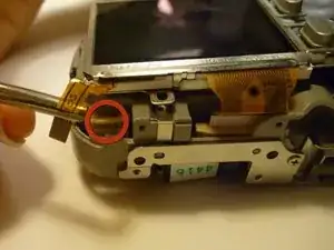
Use a forefinger and thumb to gently pull the thick yellow wiring tape out of the camera internal housing component.
-
To reassemble your device, follow these instructions in reverse order.
