Introduction
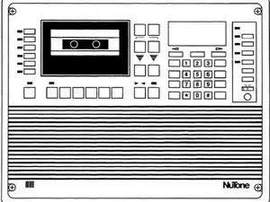
This guide outlines how to replace capacitors on the main circuit board of the IM-5006. It includes removal and disassembly. This process will require soldering.
I have attached the NuTone Service Manual and a Parts List showing the capacitor part numbers and where to purchase them.
Tools
-
-
Remove the 4 corner screws holding the intercom in its mounting bracket.
-
Tip the intercom down. It is hinged at the bottom.
-
-
-
Take photos of where each wire from the wall attaches to the intercom.
-
When removing the wires be sure to tie up any wires that might fall between the walls.
-
Remove each of the wires, noting their positions and colors.
-
-
-
The intercom is being held by two metal hinges in the back. Slide these off the screws that are holding them.
-
-
-
Note where each wire is connected on the main circuit board. Take photos of the board and the wires.
-
Disconnect each of the wires.
-
Remove the screws holding the main PC board (about 9 or 10).
-
Remove the main PC Board.
-
-
-
The main circuit board is pictured. We will be working with the capacitors that I have colored.
-
We will remove 31 capacitors. These are on the Master Station Power Supply, the Remote Station Power Supply, the Attenuator and Power Amplifier, and the Microphone Pre-Amplifier.
-
The Master power supply capacitors are in red.
-
The Remote Station power supply capacitors are in purple.
-
The Attenuator and Power Amplifier power supply capacitors are in green.
-
The Microphone pre-amplifier capacitor is in blue.
-
-
-
One at a time, remove and replace each of the 31 capacitors. By doing the complete process for each one you reduce the chance that you will mix up and place a capacitor in the incorrect position.
-
-
-
Once you have completed replacing the capacitors reassemble the intercom.
-
First attach the circuit board back to the intercom.
-
Next reconnect each of the wires on the intercom to the circuit board.
-
Next attach the metal cover back over the capacitors you replaced.
-
Now place the intercom back on the wall
-
Reattach all wires that you had disconnected earlier
-
Close the intercom and secure at each of the 4 corners.
-
Turn the power back on (at the circuit breaker panel).
-
-
-
Many times the labels on the intercom buttons have worn off.
-
Attached is a JPG of the label.
-
To reassemble your device, follow these instructions in reverse order.
2 comments
I have been an Authorized NuTone Service Center for almost 35 years. You have underestimated the difficulty of this IM5006 repair. Due to the design of the circuit boards - desoldering components is very difficult, especially for a beginner. Without a professional quality desoldering station - it is almost a certainty that a beginner will pull the via’s from the board when removing components - which ruins the circuit board.
Also, the series of Nichicon capacitors your recommend is an inappropriate choice for this unit. There are also additional components that must be replaced for the IM5006 to have any longevity after the repair.
You don’t get into the more extreme problems with this model, that now happen often due to the age on these units.
This is not a unit that the repair should be attempted by an amateur - The lack of replacement circuit boards makes working on a IM5006 a “do-or-die” repair - if you mess it up - there’s no going back - Chris
Thanks for the note. I agree that these old models present difficulties on the repair, and it is possible that during this procedure one may make the board inoperative.
I did this repair on my model at the time of my post (2015) and it has worked flawlessly since then.
Jack -


