Introduction

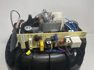
This guide will walk you through the steps to remove the fan motor of the Ninja AF161 Max XL.

  1. AHITOWTAgAAmI5JH
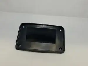
    • The back vent cover is directly above where the power cord protrudes.

  2. qTnFNgbn5nbi5WfB
    qTnFNgbn5nbi5WfB
    wJlVciBFaG5wD5hc
    • Use a Phillips #2 screwdriver to unscrew and remove four 1 cm screws from the panel.

  3. PVQw1gfiHrHoYPA1
    PVQw1gfiHrHoYPA1
    TVQEXHvnLnMLXFPe
    • Once unscrewed, remove all four screws in order to remove the back vent cover.

  4. utS2pPdCvQjf1grS
    utS2pPdCvQjf1grS
    MdE4DQDNd5EjaAYN
    • After you have the vent removed, you will see two 2.2 cm screws holding the casing in. Use a Phillips #1 screwdriver to remove the two screws.

    • Be wary that the two screws are quite tight and will require a bit of torsion to get out.

  5. CKe3a3UpMSZE2cSF
    CKe3a3UpMSZE2cSF
    Qo2iDFIOBtsQqRn6
    iUqpBRFQ1JOYUCnv
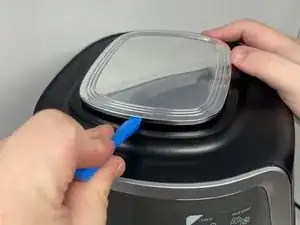
    • Use the a plastic opening tool or a similar object to wedge between the silver top and black rim.

    • Pry all four sides towards the middle with a plastic opening tool to release the tabs.

    • The tabs on the top will make sounds while being detached from the device.

  6. nWKdOot2xAnSDiJw
    nWKdOot2xAnSDiJw
    jWeCNXCYp1yRimnV
    • Unscrew the four 2.2 cm screws with a Phillips #1 screwdriver.

  7. wvyNEddFbSwKUl2U
    wvyNEddFbSwKUl2U
    PiXXlHErSbWbArd5
    • Lay the air fryer on its side.

  8. QZYfAZ6YJYsDxXZj
    QZYfAZ6YJYsDxXZj
    sbAFg551sVpMCqLf
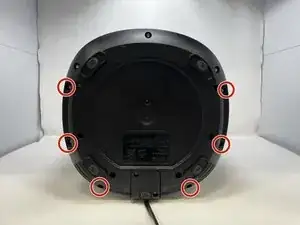
    • Remove six 1.4 cm screws with the TR15 Torx Security Screwdriver.

  9. PUQR6d3V3OGRPRDg
    • Keep the device on its side, and unscrew and remove two 1.4 cm screws with a Phillips #1 screwdriver.

  10. BYv3gYuEB1VyMWIM
    • The lid can now be lifted off. Remove by prying the bottom apart and lifting.

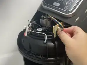
    • After lifting the lid, you will see the white and yellow wire heads that connect the air fryer display screen to the motherboard.

  11. fJjdsQ1XUHXqe5Bi
    fJjdsQ1XUHXqe5Bi
    6CVugOP6EMNtNpEJ
    IY5G4W466NZQHwqJ
    • Pinch the white tab and wire head together and pull to release the connector.

    • Take care to not bend the circuit board while attempting removal of this connector. This will damage the circuit board.

  12. 2TJIabOA14hneDm3
    2TJIabOA14hneDm3
    hcoJQfnVjqEVehYi
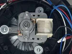
    • Remove the two 4.7 cm screws and washers using a Phillips #1 screwdriver, and then remove the silver piece on top of the motor.

    • Simply lift the motor up and gently place it to the side.

Conclusion

To reassemble your device, follow these instructions in reverse order.
Jaxon Tueller

Member since: 10/02/23

375 Reputation

0 comments