Introduction
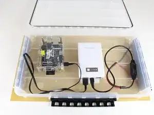
Here are the steps for creating a SolarSPELL of your own from scratch. WARNING: this build is a two-day process because the glue (Step 10) takes 24 hours to dry.
If you don't know what a SolarSPELL is, please see the SolarSPELL Device page or check out our website here.
Tools
Parts
-
-
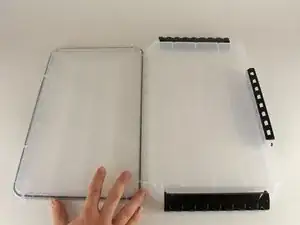
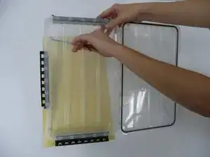
Open the clear plastic box and place face down on a drill-able surface.
-
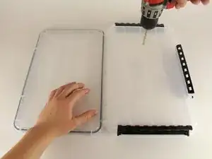
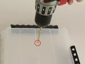
From the back of the box, drill through the indented ridge about 6 cm down from the short edge of the box with about a quarter inch drill bit.
-
-
-
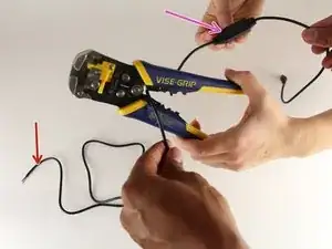
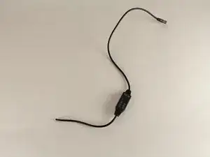
Cut the open wire side (the side that the red arrow points to)
-
Use wire cutters to cut the wire so that there is only about 3 inches left from the voltage controller (where the purple arrow is pointing)
-
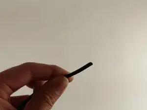
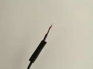
The voltage regulator should look like the one in the second picture and the end of the wire will look like the third picture
-
-
-
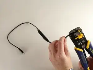
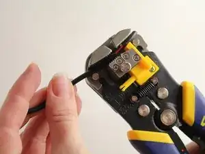
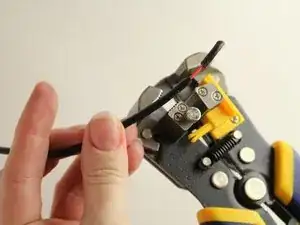
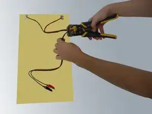
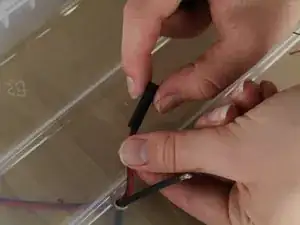
First, the outer jacket of the wire must be stripped. Keep in mind that there are two smaller wires on the inside
-
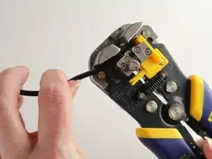
Strip about an inch of the outer wire jacket off of the wire.
-
-
-
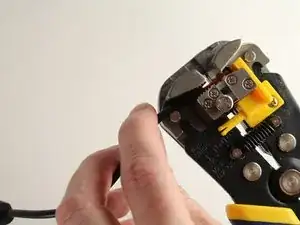
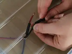
The outer jacket will now be cut loose.
-
Pull this loose piece of rubber off of the end of the wire to access the smaller black and red insulated wires below.
-
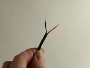
Use the wire strippers to strip the red and black insulation off of the copper core.
-
Strip about half an inch from both black and red wires.
-
-
-
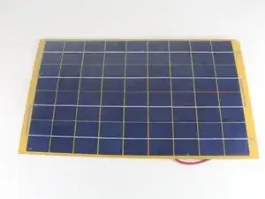
If the solar panel comes with some form of attachment, the attachment to the wires will need to be cut off leaving 10-12 inches of wire still attached.
-
This step will change depending on the type of solar panel used
-
String the wires through from the back of the panel through the hole on the outside of the box
-
-
-
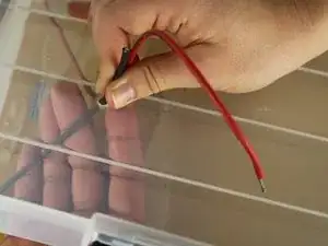
Both red and black wires will need to be stripped of the insulation to expose the copper core.
-
Refer to Step 3 for instructions on how to wire strip.
-
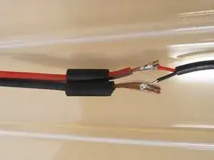
String heat shrink tubing onto both the red and the black solar panel wires separately using heat shrink that is between 3/16" and 3/32".
-
-
-
String heat shrink tubing on the wire of the voltage regulator using heat shrink that is 1/4" to 1/8".
-
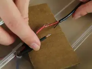
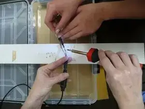
Bring the voltage regulator wires to the solar panel wires and prepare to solder.
-
Make sure you solder red to red and black to black.
-
For instructions on how to solder please visit: Soldering Skills
-
-
-
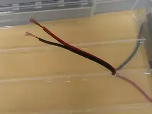
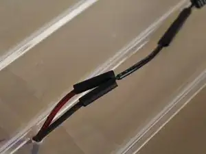
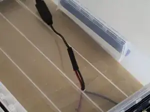
Once the wires are soldered together, pull the heat shrink from the solar panel wires down to cover the soldered part and any exposed copper.
-
Leave the heat shrink tube from the voltage regulator where it is for now, the heat shrink must be done in two separate steps.
-
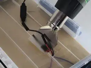
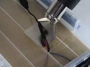
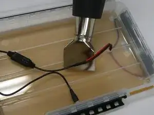
Use the heat gun to shrink the wrap strung on the two solar panel wires that are now covering the soldered connection.
-
A reflector nozzle was used on the heat gun, as shown.
-
-
-
Now, pull the heat shrink tubing that was strung on the voltage regulator down over the wires that were just heat shrunk.
-
Heat shrink this wrap until the rubber wraps neatly around the wires, ensuring the edges are sealed.
-
Pull this wire connection so that the solar panel lies tight against the back of the box.
-
-
-
Flip the box over and pull the solar panel up off the back of the box to access the back of the box, making sure the wires stay tightly pulled from the inside.
-
Assemble the glue gun based on the instructions that are included with the gun.
-
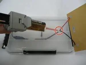
Glue the hole where the solar panel wires are strung to the inside of the box closed.
-
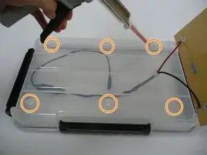
Inject the glue in quarter-sized circles on the outside edges of the box. 6 spots of glue should suffice.
-
Pull the panel down over the glue making sure it is centered on the box.
-
-
-
Download the SPELL site to a 64 GB memory card.
-
This step is not yet available.
-
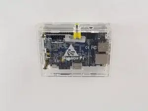
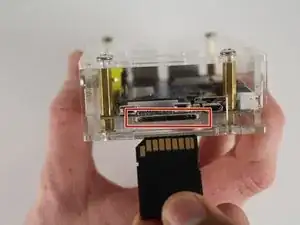
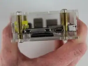
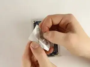
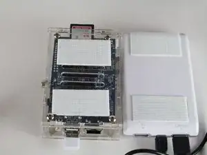
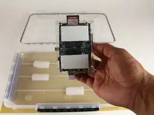
Insert the chip in the slot of the Banana Pi as shown.
-
-
-
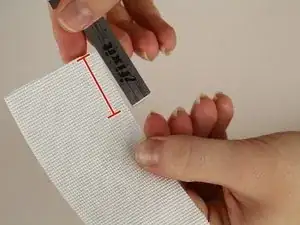
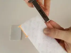
Measure pieces of the hook side of Velcro to be about 1 and 1/2 inches.
-
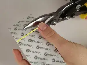
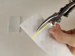
Use a pair of heavy duty scissors (sheet metal shears were used) to cut the heavy duty Velcro hook side.
-
Repeat this step three times until you have 4 strips of hook side velcro
-
-
-
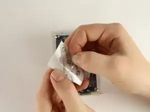
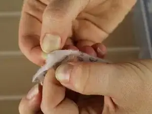
Peel the backing off of the hook side of the Velcro
-
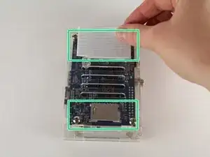
Apply the velcro to the two marked sites on the bottom of the Banana Pi
-
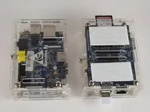
The banana pi computer will now appear as shown (before and after).
-
-
-
Again, peel the backing off of the hook side of the Velcro for the remaining 2 cut pieces.
-
Apply the other two strips of the hook side Velcro to the top and bottom of the battery.
-
-
-
Measure the Velcro loop side to about 1 and 1/2 inches.
-
Use the shears to cut a piece of loop Velcro.
-
Repeat this step three times until you have four strips of loop Velcro.
-
-
-
Open the box and place on a flat, level surface.
-
Peel off the plastic from the back of one piece of loop Velcro to expose the adhesive backing.
-
-
-
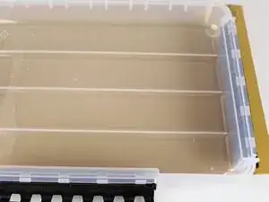
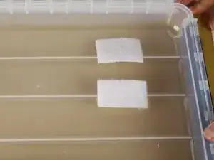
Place the piece of loop Velcro in either corner of the box, on the short side that is opposite from where the wires are connected.
-
Place the loop Velcro over top the ridge line.
-
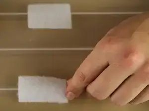
Peel back another piece of hook Velcro and place on the middle ridge line.
-
Peel back the last two pieces of hook Velcro and place in the middle of the box.
-
The first piece should go over the top ridge and the second should go over the bottom ridge.
-
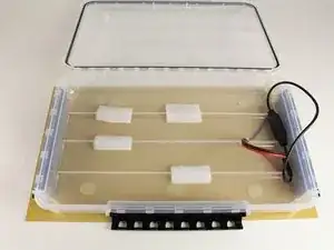
The box should now look as shown.
-
-
-
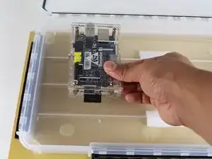
Place the Banana Pi computer on the set of hook Velcro pieces that are closer together, loop-side down.
-
This appears as the left-most set of Velcro pieces in the picture.
-
-
-
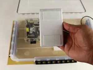
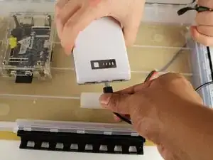
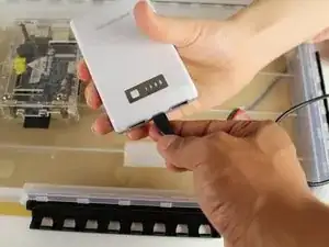
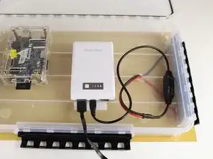
The loop Velcro attached to the battery will be placed down into the box, but first the wires must be attached.
-
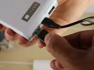
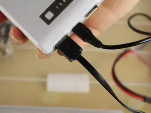
Insert the voltage regulator wire in the center hole of the battery.
-
-
-
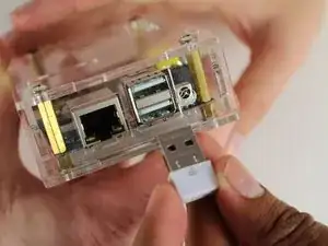
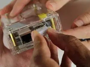
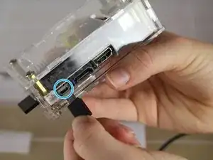
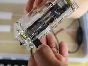
Locate the mini USB port on the Banana Pi computer.
-
This should be on the long edge with the memory card to the left and the WiFi dongle to the right.
-
Insert the mini USB plug into this port.
-
-
-
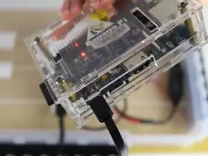
If the battery was now charged, and the computer did not turn on, the SolarSPELL will have to be taken outside in the sun so that the solar panel can charge the battery.
-
Once the SPELL is assembled, it can be turned on and any WiFi enabled device can connect to it!
4 comments
Thank you for these training instructions. Is it possible to do that training on how to download the content onto the sd card, and how to add local/own content. We'd love to add a class readers, as well as school policies and curriculum documents.
I agree with this previous comentary. I would like to know where is available the educational content in order to download it.
Thanking in advance.
Higinio from Madrid (Spain)
higbarmor@gmail.com
Hi! Have you had any of these operating long enough to observe if there’s any unexpected early fatigue on the battery? Doing pass-through charging like this where at times you have the panels generating current at the same time the Pi is operating, this likely puts a lot of burden on the battery pack. If it’s not designed for pass-through charging, it won’t even work in the first place. I made that mistake myself by buying a battery pack without checking first.
