Introduction
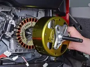
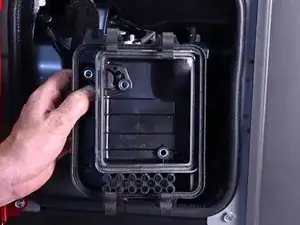
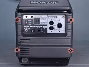
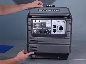
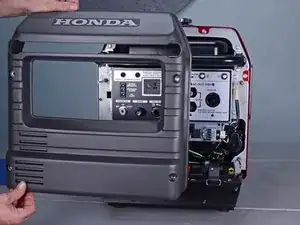
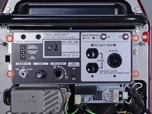
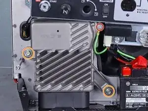
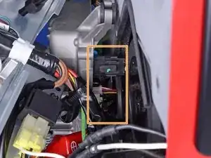
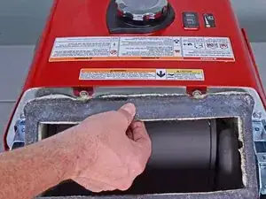
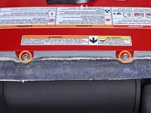
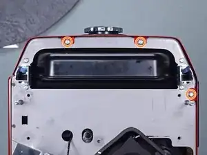
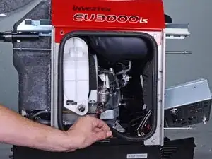
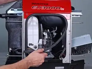
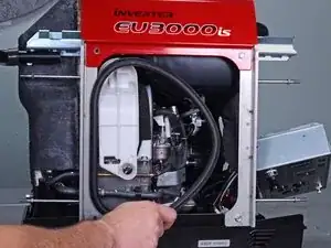
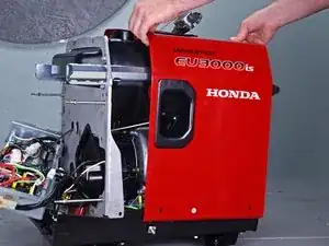
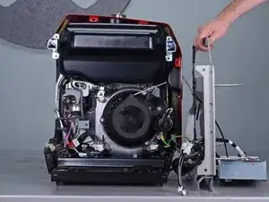
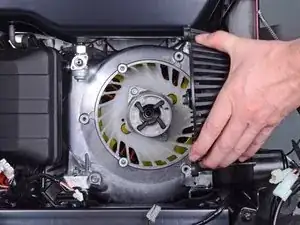
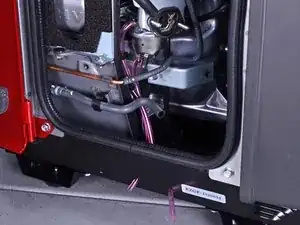
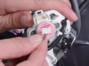
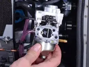
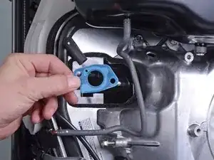
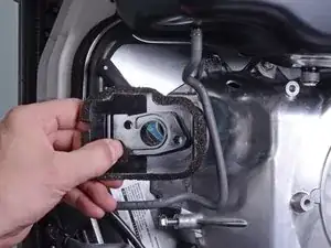
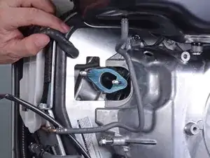
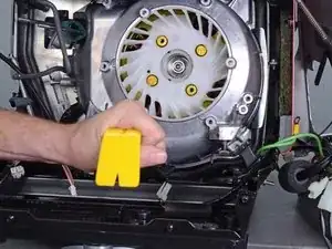
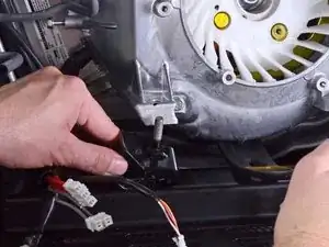
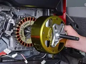
This guide shows how to remove and replace the rotor for the Honda EU3000IS1AWK 3000 watt generator.
You will need the following specialty tools in order to complete this guide:
- Flywheel puller kit with metric bolts (in order to remove the rotor)
- Long shaft (at least 5 inches) Phillips #1 screwdriver
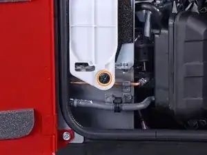
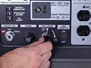
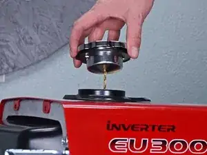
Be sure to drain the fuel tank before you begin this guide, and have containers at hand to catch any fuel spillage.
Some images in this guide may show minor discontinuities. They should not affect the overall guide procedure.
Tools
Parts
-
-
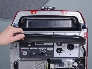
Use a large flathead screwdriver to unlock the maintenance cover.
-
Open the maintenance cover.
-
-
-
Use a Phillips screwdriver to remove the screw securing the spark plug cover.
-
Remove the spark plug cover.
-
-
-
Grab the plastic housing at the end of the spark plug wire.
-
Pull firmly to disconnect the wire from the spark plug.
-
-
-
Carefully tilt the generator to its side or back.
-
Use a 10 mm socket to remove the two nuts securing the front bushing mounts to the bottom of the generator.
-
Carefully tilt the generator back to an upright position.
-
-
-
Use a 10 mm socket to remove the three fasteners securing the air cleaner housing:
-
Two 10 mm nuts
-
One 10 mm bolt
-
-
-
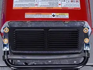
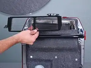
Use a 10 mm socket to remove the four capped nuts securing the front cover.
-
Remove the front cover.
-
-
-
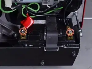
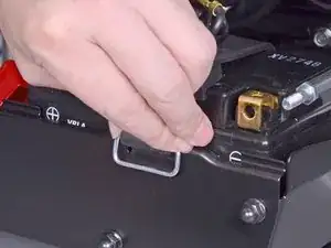
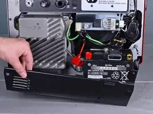
Use an 8 mm socket to disconnect the battery wires from the battery terminals.
-
Disconnect the black negative cable first to prevent the risk of shorting the battery.
-
-
-
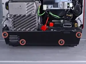
Use a 10 mm socket to remove the four capped nuts securing the lower plate.
-
Remove the lower plate.
-
-
-
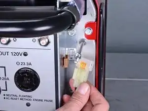
Insert a flathead screwdriver into the top of the brown fuse clip in order to release the fuse holder.
-
Detach the fuse holder from the brown clip.
-
-
-
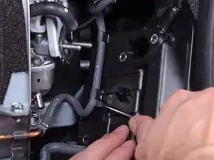
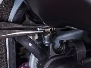
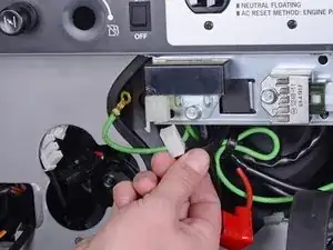
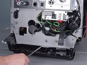
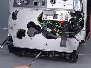
Use a long shaft Phillips screwdriver to remove the deeply recessed screw securing the fuel cutoff switch.
-
-
-
Remove the following bolts securing the inverter:
-
One 8 mm ground bolt
-
Three 10 mm bolts (one behind the control panel)
-
-
-
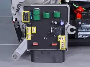
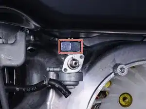
Reach behind the inverter along the edges and disconnect the six connectors from the back of the inverter.
-
The third image shows the locations of all six sockets on the inverter.
-
-
-
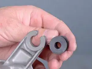
Squeeze the mount and remove it from the inverter.
-
Repeat the procedure with the remaining mounts and transfer them to the replacement inverter.
-
-
-
Use a 10 mm socket to remove the four capped nuts securing the rear cover.
-
Remove the rear cover.
-
-
-
Use a 10 mm socket to remove the four bolts securing the muffler protector.
-
Remove the muffler protector.
-
-
-
Pull the muffler shroud slightly away from the frame to access the top frame bolts.
-
Use a 10 mm socket to remove the two bolts securing the top edge of the cover.
-
-
-
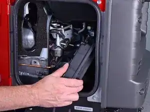
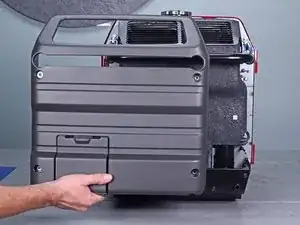
Use a 10 mm socket to remove the four bolts from the maintenance cover side.
-
Remove the maintenance cover.
-
-
-
At this point, it may be helpful to temporarily re-attach the control panel back onto the front frame with some 10 mm bolts.
-
-
-
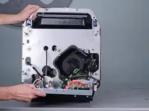
Insert the edge of a large flathead screwdriver under the bottom edge of the front frame.
-
Pry up and outward to release the bottom edge of the front frame.
-
-
-
Remove the recoil starter and move it out of the way.
-
Be careful not to lose the metal collar in each of the recoil starter's bolt holes.
-
-
-
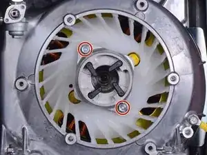
Use a 10 mm socket to remove the two bolts securing the starter pulley.
-
Remove the starter pulley.
-
-
-
Use a 10 mm socket to remove the bolt securing the air cleaner housing bracket.
-
Remove the air cleaner housing bracket.
-
-
-
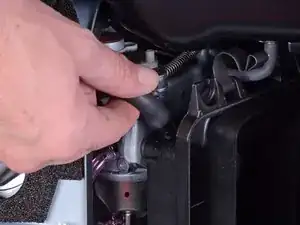
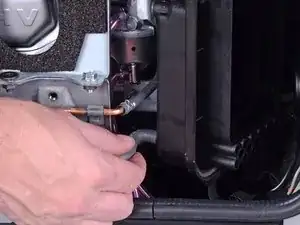
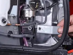
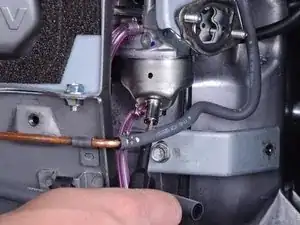
Use pliers to squeeze and loosen the hose clamp securing the carburetor fuel line.
-
Pull and disconnect the carburetor fuel line from the petcock assembly.
-
-
-
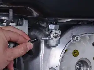
Use a large crescent wrench to loosen the petcock assembly from the fuel tank.
-
Remove the petcock assembly.
-
-
-
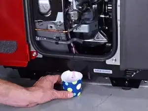
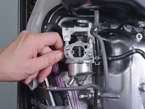
Place a container below the carburetor drain tube to catch the excess fuel.
-
The carburetor drain screw is located at the bottom of the carburetor.
-
Use a flathead screwdriver to loosen the brass fuel drain screw until fuel begins to drain out of the carburetor.
-
Once you drain the fuel bowl, re-tighten the fuel drain screw.
-
-
-
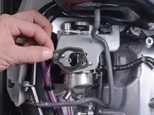
Disconnect the throttle control connector from the top of the carburetor.
-
Unwrap the throttle control wires from the carburetor.
-
-
-
Use a 10 mm socket to remove the seven bolts securing the fan cover:
-
Four bolts on top
-
One recessed bolt in the bottom left corner
-
Two bolts in the bottom right corner
-
-
-
Insert a pry bar underneath the fan cover.
-
Pry upwards to lift the generator assembly slightly.
-
-
-
As you lift the generator assembly with the pry bar, maneuver and remove the two generator mounts from their recess.
-
-
-
Attach a flywheel puller to the rotor and use it to loosen the rotor.
-
To prevent the rotor from spinning, insert a flathead screwdriver into one of the rotor slots and brace it against the ignition coil bracket.
-
To reassemble your device, follow these instructions in reverse order.
