Introduction

  1. W5Qjc4ww3xIQyXw6
    W5Qjc4ww3xIQyXw6
    Vj2DbLLFUMAVDKfZ
    GmGeWYy2cZ1Q11U4
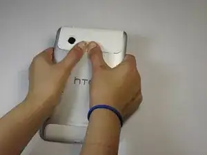
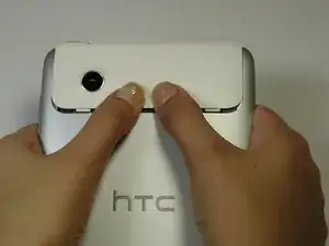
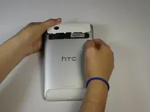
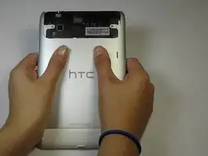
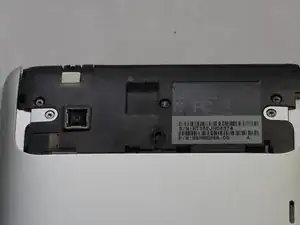
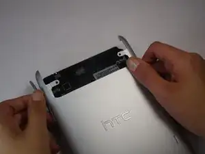
    • Apply pressure along the bottom of the white panel containing the camera and push upwards.

    • It may take some effort, but it will smoothly slide off.

  2. FcVxhTidqpxwtNiW
    FcVxhTidqpxwtNiW
    DHYXB33QXl5NOvFR
    IfbooLdQd6K1YauU
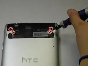
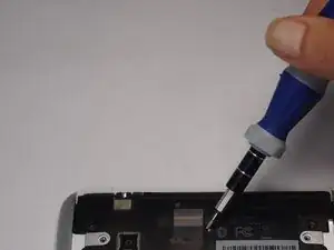
    • Unscrew the four of 3.5mm Torx T5 screws that run along the sides of the exposed innards.

    • All screws in the device will use the Torx T5 screwdriver, so keep it handy.

  3. JnSLvv2Q6E3OoRfb
    JnSLvv2Q6E3OoRfb
    3GUCIJKkvTcX1hTD
    senNKoBaY5mrbUXB
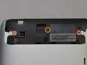
    • Remove the black protective piece of plastic by sliding it upwards.

    • Remove the two 3.5mm Torx #5 screws holding the protective plastic down on along the sides.

    • A center 3.5mm Torx screw will be covered by "VOID" sticker.

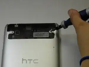
    • Either remove the sticker or jam the screwdriver into the screw, and remove the screw.

    • Remove the protective panel by sliding it upwards.

  4. V6YkELdKMjtYKUAB
    V6YkELdKMjtYKUAB
    OAmefsMtKhmayvKW
    • Before removing the back cover, apply some scotch tape to the volume buttons to prevent them from falling out of the back panel.

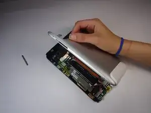
    • Use a plastic opening tool to lever up the top half of the cover.

    • Lift the back panel up and remove it from the device.

  5. gGPIeMajL4rAGncX
    gGPIeMajL4rAGncX
    iCbBrNJsAyZAoxyF
    • Gently unfold the black tape along the top that covers the cable attachment points.

    • Leave the tape partially attached so that it can be easily re-attached.

  6. VidCnSW36aiDAoCQ
    VidCnSW36aiDAoCQ
    RPmyVvFONrOtJIAo
    bCfl2BMslrpVxLMv
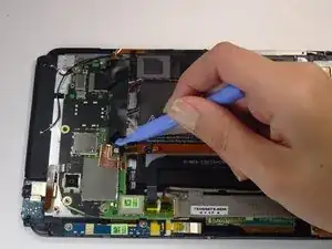
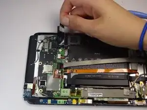
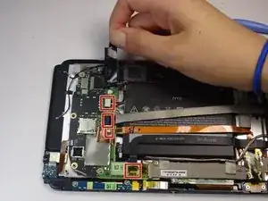
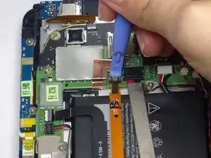
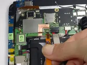
    • Use the tip of a spudger as a lever to disconnect the four cable connectors.

    • Gently pull out these cables after releasing the back piece.

  7. qbcsqvFuxPD4En6f
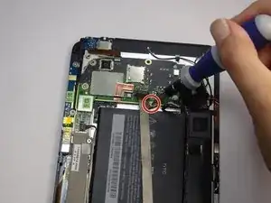
    • Remove the single 2.5mm Torx T5 screw holding the battery down along the top side.

  8. MgdW1liPARQ2rTEy
    MgdW1liPARQ2rTEy
    JicP3R6Oh4e3Rd66
    oEibiLnJIkpgMNQv
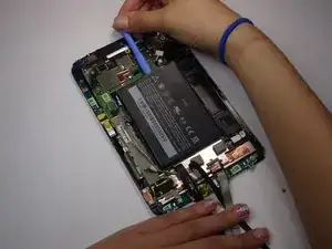
    • Wedge the flat end of a spudger inbetween the battery and the front panel assembly.

    • Run the flat end of a spudger along the top edge of the battery to separate it from the adhesive securing it to the front panel assembly.

    • If you encounter any resistance from the remaining adhesive, simply use the flat end of a spudger to remove the excess adhesive.

  9. Hi6nGWD4bFNuUF4a
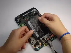
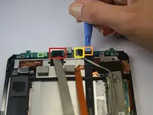
    • Use a spudger to unclip the the wires attached to the power jack

    • The clips have a white or black relief tab that, when pressed, releases the wires.

  10. H1O2wCIMBFZCDQyK
    H1O2wCIMBFZCDQyK
    FpKLiTXVbdIqNxqb
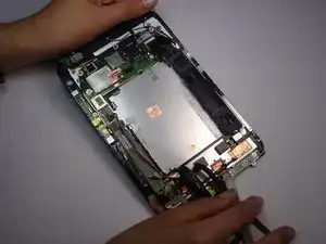
    • Remove the two 2.5mm Torx T5 screws from both sides of the power jack panel.

  11. rmUHSKqj2EbFhgQH
    rmUHSKqj2EbFhgQH
    YWjvZZ6bgv3G5gee
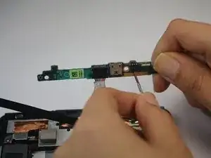
    • Gently remove the power jack panel.

Conclusion

To reassemble your device, follow these instructions in reverse order.
Joshua

Member since: 07/10/14

185 Reputation

0 comments