Introduction

After completing the Outer Shell Disassembly guide, this process will aid in replacing the HP Photosmart c4780 motherboard with minimal technical requirements.

  1. sCvxASM2BTUNfVMf
    sCvxASM2BTUNfVMf
    EtLwhCRCqonNEGSk
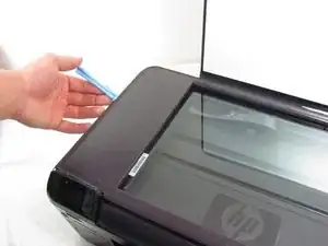
    • Unplug the device from any energy sources.

    • Lift the top cover of the scanner.

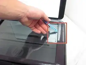
    • Use a plastic opening tool to remove the plastic frame surrounding the glass.

  2. VNrMdR6aSSgpgFKy
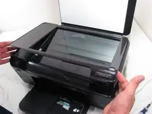
    • Carefully pull the frame away from the glass.

    • If it doesn't remove easily, use the iFixit Opening Tool again to pry stuck sections.

  3. La4NjOYFGpuEGHdT
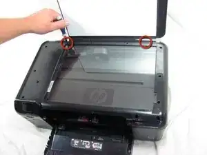
    • Use a T10 screwdriver to unscrew the two screws that fasten the frame to the printer hood.

  4. VZVQv5DxD6Q6xkwE
    VZVQv5DxD6Q6xkwE
    xCmMqeCQodwRBHpy
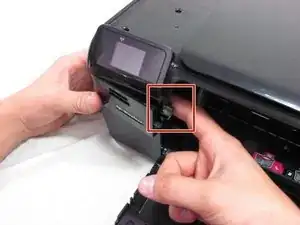
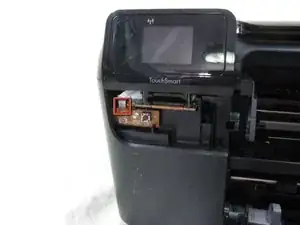
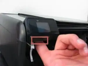
    • Put your finger behind the panel with the power button.

    • Then, pull the piece outwards.

  5. 4IgJZ636eEnD1oEA
    4IgJZ636eEnD1oEA
    H4Oqgq6LxkTpGZWT
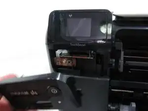
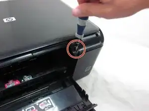
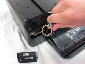
    • Unscrew the screw inside the power button panel space.

    • Then, unscrew the screw that is across the printer slider.

  6. R5ROP3WPApla5nps
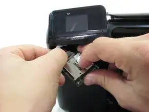
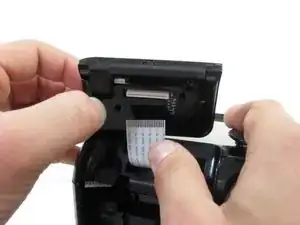
    • Pull the white circuit board outwards which is located under the small screen.

    • Unplug the small ribbon cable from the circuit board.

    • Be careful when you unplug the ribbon cable not to use too much force. Using too much force may damage or rip the cable.

    • Unplug the small ribbon cable from the circuit board. Be careful when you unplug the ribbon cable not to use too much force. Using too much force may damage or rip the cable.

  7. KX5A1MUNrSRLJLMS
    KX5A1MUNrSRLJLMS
    BweAaTKHfGHwQZTQ
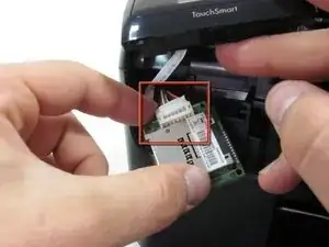
    • Pull the memory card reader's circuit board out.

    • Detach the white wiring connector from the back of the circuit board.

    • You may need to use a finger nail or a plastic opening tool to detach the white wiring connector from the circuit board.

  8. DhRjmbr3bJtfSrK1
    DhRjmbr3bJtfSrK1
    U54hLGXlQGpDuGSr
    • Put your finger behind the small screen.

    • Then, pull it up.

    • Do not hesitate to use force to remove the TouchSmart panel.

    • Disconnect the ribbon cable from the small screen.

  9. LCqFTKjM3obx4CaN
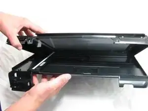
    • Pull the printer hood upward.

  10. TGZIdpSkFHeDRQHL
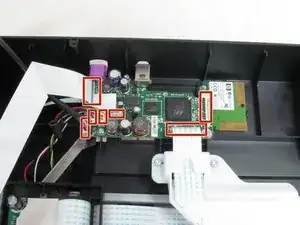
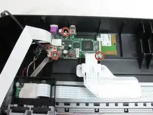
    • Remove the three uncovered T10 screws from the motherboard.

  11. 3JYRAVwAvZPZTTyH
    • Gently remove the seven cables that are attached to the motherboard using a plastic opening tool.

  12. FBTvUCNVjm2PquqZ
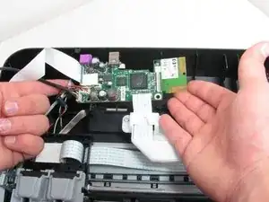
    • Gently lift motherboard out of the slot.

Conclusion

To reassemble your device, follow these instructions in reverse order.
garrett hall

Member since: 26/09/12

49 Reputation

0 comments