Introduction

  1. d1o5PLWpeYGyQ2Uf
    d1o5PLWpeYGyQ2Uf
    HXEURXfC2Bvy1ToT
    TPqMgIxTl2CLEYQb
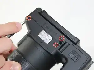
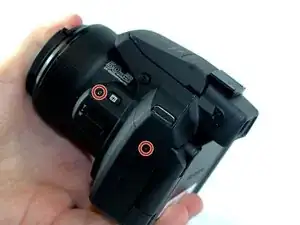
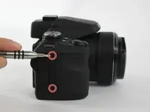
    • Remove the 7 screws on the perimeter of the camera body.

  2. GVIXWYLrntRW1KYC
    GVIXWYLrntRW1KYC
    OjaUJvAwbnIUW2lc
    Hq5kP3ZduxKtIA5u
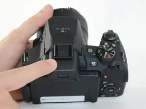
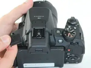
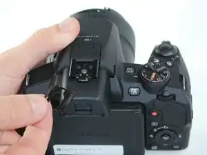
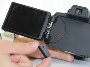
    • Remove the flash accessory cap.

    • Remove the spacer covering the screws under the flash accessory cap.

  3. hRudAFfPdSpUY3bg
    hRudAFfPdSpUY3bg
    iCLJuVZG1s3LyO1Z
    3cf1C6oGXkShMQe6
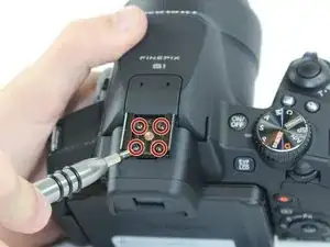
    • Remove the 4 screws from the inside of the flash accessory slot.

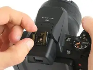
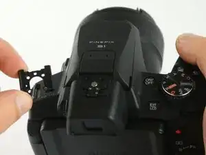
    • Pull off the flash accessory slot.

  4. PdSi5BRnAwDnTuDY
    PdSi5BRnAwDnTuDY
    J4UrDNC6y3EMNLKC
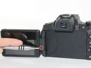
    • Remove the screw from LCD Screen hinge cover.

    • Remove the LCD Screen hinge cover.

  5. FNmma5QsatCnoe3x
    FNmma5QsatCnoe3x
    M6JbVe2AdjdvFkaN
    GPGeGVoYLljYffJH
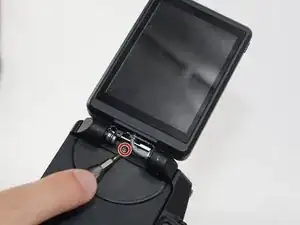
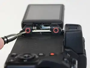
    • Remove the 3 screws located on the LCD screen hinge.

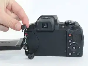
    • Remove the caps from both ends of the LCD screen hinge by lifting them off.

  6. 2Goengke4bjPSHiG
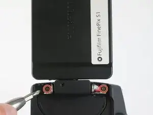
    • Remove the 2 screws from under the LCD hinge caps.

  7. nkvnTJ5nCFvesJxC
    nkvnTJ5nCFvesJxC
    3CUUGSYwFblHuYlP
    Ew6gRpDShqYhXeuQ
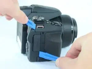
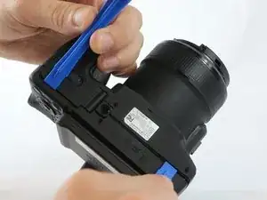
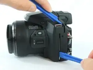
    • Pry apart the back body from the rest of the camera.

  8. vVsBZck6Ru2OVmyO
    vVsBZck6Ru2OVmyO
    XT4BcBuRA5LPBNIV
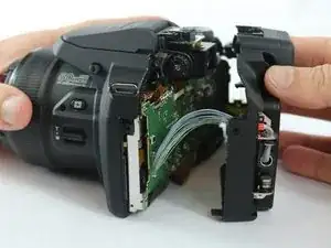
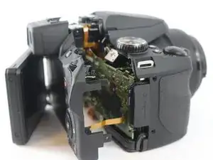
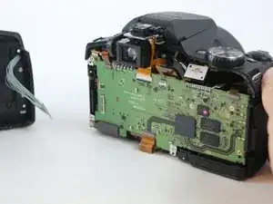
    • Carefully pull the back body off of the camera.

    • Make sure to not yank off the connections from the body to the motherboard.

  9. EBEP6OVkGw5X4E6x
    EBEP6OVkGw5X4E6x
    2IwwSrF2GFBavh4p
    GOnlfOgG53rWJOAL
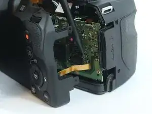
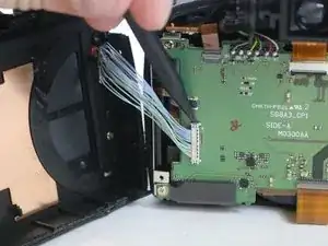
    • Use a spudger to lift up on the tab, releasing the yellow wire strip.

    • Use a spudger to lift up on the side tab, releasing the blue wire connection.

Conclusion

To reassemble your device, follow these instructions in reverse order.
Brandon Benavente

Member since: 15/02/16

677 Reputation

0 comments