Introduction

Broken viewfinder? Follow the steps below to get your camera working like new.

  1. QnrkdI5kGosUvUqa
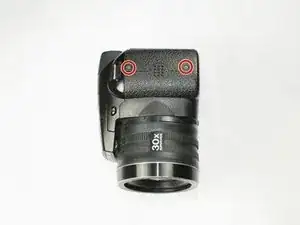
    • Remove the two 3.5 mm Phillips #1 screws in these positions on the left side of the camera with a screwdriver.

  2. doI6GQFytLuW1CA3
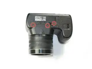
    • Remove the three 3.5 mm Phillips #1 screws in these locations on the bottom of the camera with a screwdriver.

  3. T3BCXmTbwr3ALmoZ
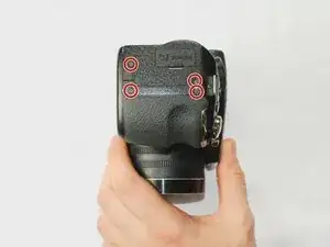
    • Remove the four 3.5 mm Phillips #1 screws in these positions on the right side of the camera with a screwdriver.

  4. swKcJX6DF3a4BWVd
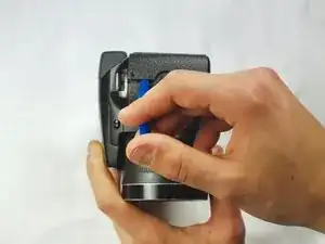
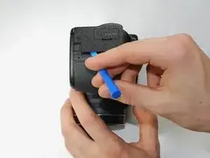
    • Use a plastic opening tool to separate the back panel from the camera on the left side.

  5. 1LCQkQmcLYfQCiRb
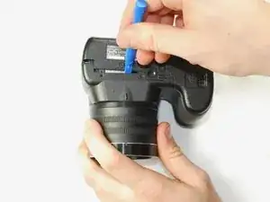
    • Use a plastic opening tool to separate the back panel from the camera on the bottom.

  6. JTxMR3YWVQssQesf
    JTxMR3YWVQssQesf
    ADLVuNxXMIcWf3FJ
    • Use a plastic opening tool to separate the back panel from the camera on the left side, then remove the back panel from the camera.

  7. mqypm3vxY34URmZm
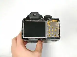
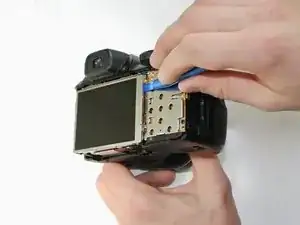
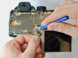
    • Use a plastic opening tool to separate the LCD screen from the camera.

  8. OCTh3IgkSaLBCRAW
    OCTh3IgkSaLBCRAW
    AywvOmEqNEwcDdUZ
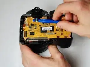
    • Flip up the black tab holding the LCD ribbon wire in place and remove wire.

  9. oB2fln1jTZJ13RSF
    oB2fln1jTZJ13RSF
    WKCLVAKWxWxkAHwn
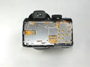
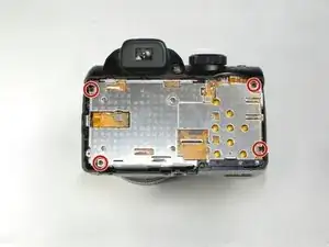
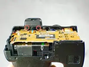
    • Remove the highlighted 2.7 mm Phillips #1 screws to release the metal cover.

  10. Qqm4eKKf2N5Nrljh
    • Turn the camera on its side and remove the highlighted 2.7 mm Phillips #1 screws.

  11. VqqEgJxBpNZGBJMd
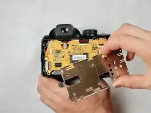
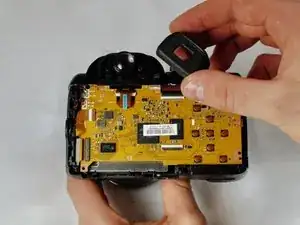
    • Lift and remove viewfinder cover

  12. F3ITg6pW5yYZJtoj
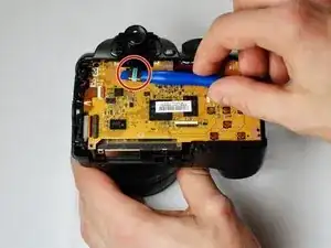
    • Use the plastic opening tool to remove the ribbon wire from inside the camera

  13. l1sjdGOSOUbfr52X
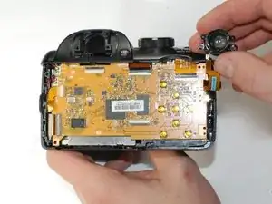
    • Remove the viewfinder assembly from the camera

Conclusion

To reassemble your device, follow these instructions in reverse order.
Vicente Rios

Member since: 26/01/17

708 Reputation

0 comments