Introduction

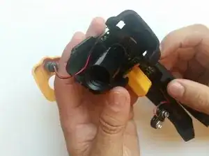
This guide will show how to remove everything from the motherboard and have it by itself for replacement. This guide should only be necessary if nothing else works. It is a last resort as the motherboard is the least likely to malfunction. The tools needed are a screwdriver and soldering iron. The soldering iron will become very hot, so that is a potential hazard. For those who are not comfortable soldering, there is a link to a soldering guide in the Troubleshooting section of the device page.

  1. obB3lByTCoqYvRUO
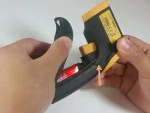
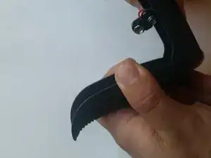
    • Pull the battery cover away from the handle by gripping near the thumb groove.

  2. ctmGSaQ2TGtifROG
    • Gently pull the battery out of the handle.

    • Excessive force could damage wires.

  3. a2LiF3NQYAQUaPYB
    a2LiF3NQYAQUaPYB
    eLLJoJqEoxf2FdSI
    • Disconnect the battery by pulling the connector away from it.

    • Positive first

    • Negative second

    • When replacing the battery, this order is reversed.

  4. 1FA4PUHdCJVkbtZf
    1FA4PUHdCJVkbtZf
    sCEGVNcVRN5YjESj
    • Remove the battery cover from the device by pulling it straight out.

  5. 2pkWvb1qcFBSAqnd
    2pkWvb1qcFBSAqnd
    15wgfHxNNV4sxM3j
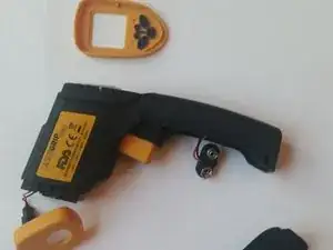
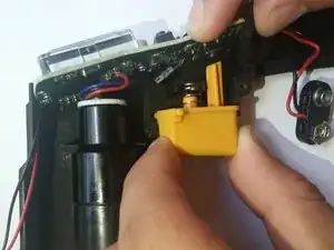
    • Using the plastic opening tool remove the front and rear yellow covers.

    • When removing the back cover, be careful not to lose the buttons as they are not connected.

  6. lWONdPGophDfPJTo
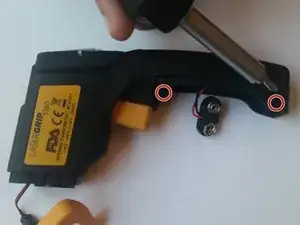
    • Remove the two 3.1 mm Phillips #0 screws.

  7. 4RWtuOUvAwpZZp2F
    4RWtuOUvAwpZZp2F
    YEQFh6oXMhtSdxgh
    • Pull the two halves apart.

    • Be careful not to lose any components on the inside.

  8. kLZHcrQCSHEtn3RP
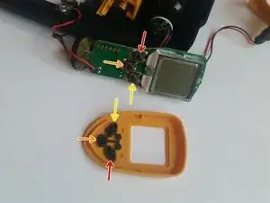
    • Realign the buttons with the button terminals.

    • Red terminal to red button.

    • Orange terminal to orange button.

    • Yellow terminal to yellow button.

  9. PArZmmUkKXKSgBbb
    PArZmmUkKXKSgBbb
    mOPTdZYgxcILEZTs
    • Carefully pull the trigger out.

    • The trigger is spring loaded, so be careful that you do not lose the spring as you pull the trigger out.

    • To put the trigger back in, align the peg with the hole in the handle and align the shaft with the button terminal.

  10. TnTkpnNcELUmgLXG
    • Pull the motherboard out of its slot in the device.

  11. IxslI5UeQubVsMnZ
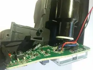
    • Use a soldering iron to melt the solder that holds the wires for the laser to the motherboard.

    • Soldering irons are hot and should only be handled by those who know what they are doing and are wearing proper safety equipment. There is a link to a soldering guide in the Troubleshooting section of the device page.

  12. pu1NCcZJuRWjrfAl
    • Pull the motherboard out of its slot in the device.

  13. on1wXWxNKLPnuPRN
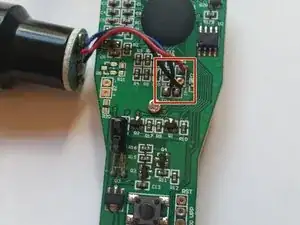
    • Using a soldering iron, melt the solder that holds the wires for the sensor to the motherboard.

    • Soldering irons are hot and should only be handled by those who know what they are doing and are wearing proper safety equipment. There is a link to a soldering guide in the Troubleshooting section of the device page.

  14. BJhokEH53Bn1IEPm
    • Pull the motherboard out of its slot in the device.

  15. xfEtxE3HJCMmOrNW
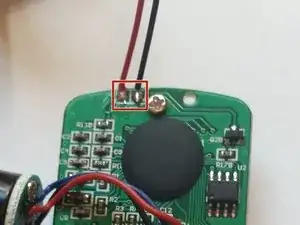
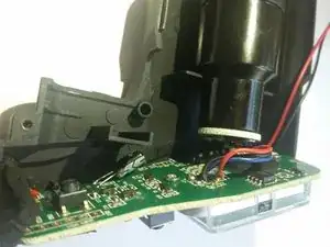
    • Use a soldering iron and melt the solder where the battery connector's wires are attached to the motherboard.

    • Soldering irons are hot and should only be handled by those who know what they are doing and are wearing proper safety equipment. There is a link to a soldering guide in the Troubleshooting section of the device page.

  16. anWvmSi3GipYqPEW
    • Carefully pull the motherboard out of its slot in the body of the device.

  17. RBBdObYTZbPb1CTg
    RBBdObYTZbPb1CTg
    Z2ChJrpUjVpY2CWG
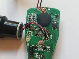
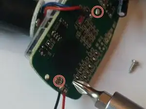
    • Unscrew the two 3.4 mm screws on the motherboard.

  18. cLpClHfdQBCXqJMQ
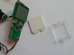
    • Take off the cover and separate the parts.

    • All of these parts are fragile and mishandling them may cause damage.

Conclusion

To reassemble your device, follow these instructions in reverse order.
Patrick Crawford

Member since: 27/08/15

741 Reputation

0 comments