Introduction
This lock machine had become stuck completely after already having difficulty turning.
Video is from after fixing it.
-
-
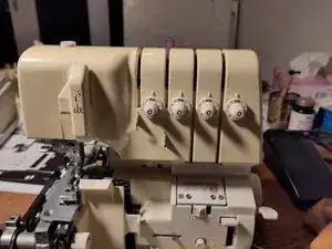
The eclipse lock machine with two needles; this one stared moving with difficulty, and had blocked entirely.
-
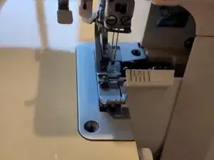
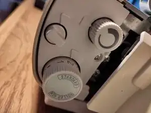
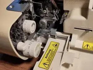
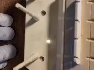
This picture has the left cover removed, by removing the screws at the bottom, and two in the metal pate at the top, see second picture. One Phillips (already removed on the photo) and one Allen key.
-
This machine is easy to disassemble as long as the drivetrain is not involved. It wasn't necessary to disassemble the drivetrain in this case. The drivetrain is fixed very tightly, and is also difficult to reassemble.
-
-
-
The bottom panel is easy to remove by removing the four screws in the feet. It exposes the bottom part of the drivetrain. It is best to re-attach the feet after removing the panel, so that the machine stands stable during further disassembly.
-
Here it was possible to see that that the axle could still rotate a bit. It is very difficult to assess what part blocked the movement.
-
Early on a needle was found falling out of the machine with the tip broken off, so after any removal of a panel all visible parts ahve been inspected to find whethe this tip would be blocking the movement somewhere.
-
-
-
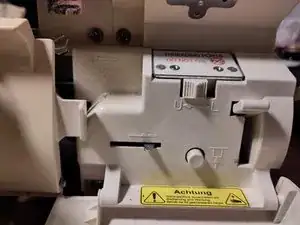
The small side panel is easy to remove, via 1 screw.
-
The front bottom left panel s a bit tricky to remove; it is best to start with the small door on the left, on the second image, where two screws at the bottom keep it in place.
-
Once this has been removed, two more screws at the bottom can be removed to disassemble the right panel. it als has a small hook on the tight, that needs to be dislodged from a pneumatic tube.
-
-
-
Removing the bottom panel reveals a number of screws at the bottom that allows removing more side panels. Here the side panel on the left side of the machine is removed.
-
The vacuum is for illustrative purposes only; this particular one is not very effective.
-
-
-
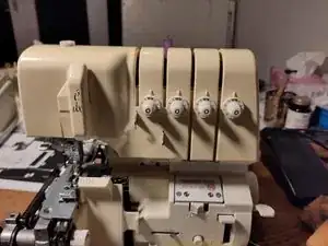
Removing the top hood shown here involves removing a few screws at the back, pulling the four dials of at the front, and removing the "e/dx" cover by pinching it, thus providing some slacking for the teeth that normally snap them in place.
-
-
-
After a lot of gently pushing and pulling, it was found that the rods that drive the needle at the top of the machine had become blocked. With some force they have been remobilised, fixing the machine.
-
The suspected needle point has not been found.
-
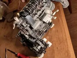
Some small auxiliary systems have been removed as well, e.g. the threading system. The main mechanical operations are fixed very strongly, and are most likely very difficult to reassemble.
-
To reassemble your device, follow these instructions in reverse order.
