Introduction

A broken switch means electricity is not flowing through your device. Removing and replacing this component requires soldering. Check out this soldering guide for instructions.

  1. OFO5SRinoVokGvoK
    OFO5SRinoVokGvoK
    jsxBPIw2MoOSiu4A
    kSWShXMUwwDUSSkA
    • Unplug your food processor before starting any disassembly.

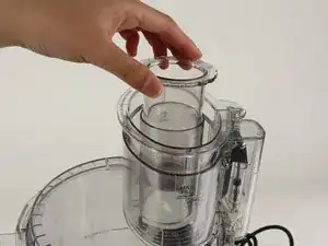
    • Remove the small pusher by rotating it clockwise and lifting up.

  2. THlyFpesCnWRLVqS
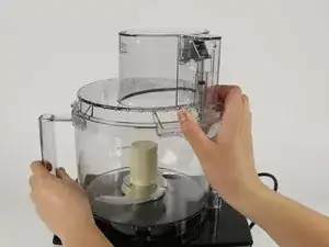
    • Remove the large pusher by grabbing its sides and pulling up.

    • There may be a clicking sound from the safety feature being disengaged in this step.

    The little white thing that pushes down broke

    Mr. potato -

  3. QAlfxHf4WNryKUD6
    QAlfxHf4WNryKUD6
    gUVCoPwJhgnVIpBE
    laBrJrkuhbPEbFpL
    • Remove the lid from the bowl by turning it clockwise and lifting.

  4. npb3Nb6GaDKdwpyq
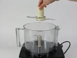
    • Take out the blades by grabbing the plastic center piece and lifting up.

    • Avoid contact with blades as they are extremely sharp.

  5. AdOX2PUUHSe5C3FQ
    AdOX2PUUHSe5C3FQ
    duKHZZcYPFJLQtMx
    Da3UfggLQGgGpnMY
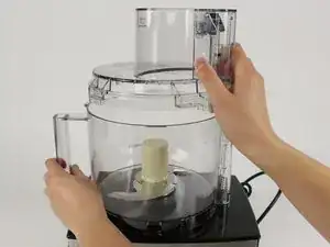
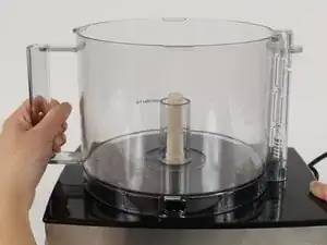
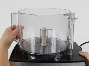
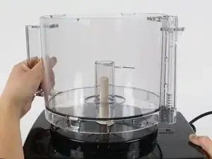
    • Position the handle of the bowl so that it is on your left.

    • Grab the handle and push clockwise. Lift up the bowl to remove it.

    It seems so simple and obvious. Thanks for your help!!!

    Carrie Shirley -

  6. PSQoMWypXxqWV6AC
    PSQoMWypXxqWV6AC
    1QcruKNcLAwQsDJF
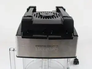
    • Turn the food processor's base upside down by lifting it up and turning it over.

    • Position the base so that the on and pulse buttons are facing you.

    • Place the base on top of the food processor's bowl to keep the base from wobbling while you work on it.

  7. BfhJEjwPcr1gTQvY
    BfhJEjwPcr1gTQvY
    K5E32dtH5bPTtvXv
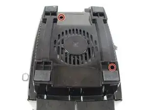
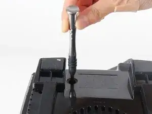
    • Remove the two 13.0mm screws that hold down the casing with a Phillips #2 screwdriver.

  8. aPOjkR2jPMqMCZUU
    aPOjkR2jPMqMCZUU
    Cjtf5nnUEZ1OtWpP
    qQhspumpCuTk5Yg1
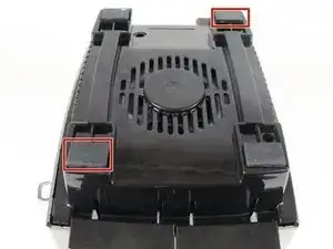
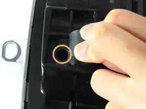
    • Lift up the front left and the back right rubber feet by pulling back the rubber with your fingers.

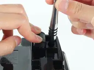
    • Remove the 13.0mm screw under each rubber foot with a Phillips #2 screwdriver.

  9. WhmudNRONIAJsVGf
    WhmudNRONIAJsVGf
    GkDwooTY1aXQ3uaA
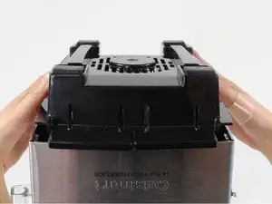
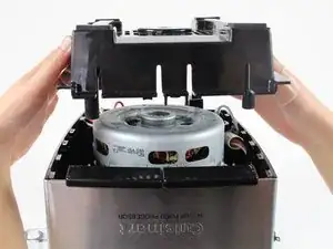
    • Lift off the back casing by raising it upward.

  10. LLxySbGMymuIH6ax
    LLxySbGMymuIH6ax
    XCMuJmNJHQXfscoR
    ChiMJeYQLHLNNyMf
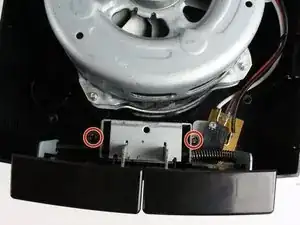
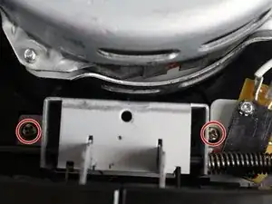
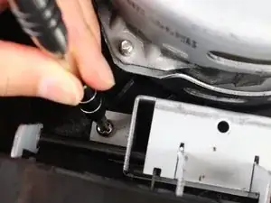
    • Remove the two 13.0mm screws that are holding down the button assembly using the Phillips #2 screwdriver.

  11. LyMMqce3EJ2A4LNP
    LyMMqce3EJ2A4LNP
    yc3XnnSMJMlFDfdQ
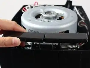
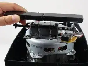
    • Lift out the button assembly by pulling up.

  12. yhyGfWCA1kT5fDRu
    • Remove the two 5.5mm nuts with a 5.5mm nut driver.

  13. ABK5SyiaZhJbWVsr
    ABK5SyiaZhJbWVsr
    i5LGrfQUnqddBYIr
    FRYIDD6AdoeMk2xt
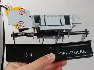
    • Remove the two 13.0mm screws that hold the switch to the button assembly with a Phillips #2 screwdriver.

    • The screws have glue in their threads, so this step might require a little extra force.

    • Slide off the switch and yellow plastic to remove the button assembly.

  14. vfTkIGHoMxHS4Ogf
    vfTkIGHoMxHS4Ogf
    BihWhsAo5W2aNQhk
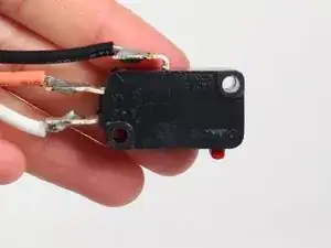
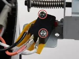
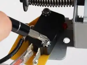
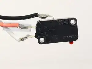
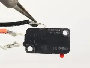
    • Desolder the white, black and red connections from the switch by using a soldering iron.

    • Refer to the soldering guide for extra help.

    • For reassembly, the new switch's connections will have to be soldered on.

Conclusion

To reassemble your device, follow these instructions in reverse order.

Sonya Dick

Member since: 05/10/16

352 Reputation

One comment

You had me until the desoldering, maybe I’m just a wimp! Thanks anyway … good description!

dmdudek -