Introduction
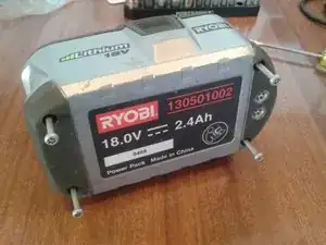
This guide applies to Ryobi One+18V Li-ion Battery (130501002), but should also have more general application. This guide will show you how to disassemble the battery pack and check the cell balance and rebalance the cells if necessary.
The battery should normally measure about 18V across the terminals (21V max). If it reads about 12V, then it is likely the battery protection circuit has activated because of cell imbalance. (Those were my symptoms.)
Cell re-balance could also help if the battery isn't taking a full charge (not showing green on the fuel guage button).
The time estimate for this guide is for disassembly and cell balance measurement. Cell rebalance charge time is extra.
CAUTION: Battery disassembly exposes high current circuits. Be careful!
This battery is of 2P5S configuration (sets of 2 parallel cells, 5 sets in a series string). It uses Sanyo 18650 Li-ion cells.
Tools
-
-
CAUTION: Battery disassembly exposes high current circuits. Be careful!
-
Remove the four T15 security screws from the bottom.
-
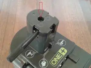
Remove the one T10 screw on the top.
-
-
-
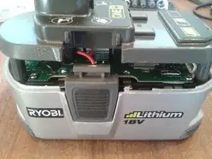
Lever the cover clips to remove the top cover. Leaver up so the base pops out.
-
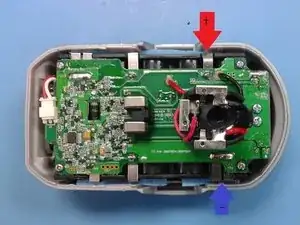
Using an insulated instrument, lever the battery terminal assembly down inside the top cover.
-
CAUTION: use of a metal instrument for the above step risks shorting the battery contacts.
-
-
-
Once there is enough gap, reach in and hold the battery terminal assembly, while sliding off the top cover.
-
The battery catch clips on the sides can be removed if you want.
-
-
-
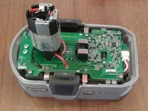
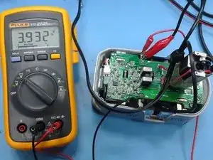
With a Digital Multimeter (Volt Meter) set to DC Volts, measure the cell balance. The nickle straps are good test points. Note the cell voltages.
-
Cell 1: TP6 to CL1
-
Cell 2: CL1 to CL2
-
Cell 3: CL2 to CL3
-
Cell 4: CL3 to CL4
-
Cell 5: CL4 to CL5 (Battery Pos)
-
The cell voltages should be in the range 3.0V to 4.2V. The cells should all read about the same, say 3.9V. If the cells are more than 0.1V different, then cell imbalance could be a problem for your battery pack.
-
-
-
Use a Benchtop Power supply with adjustable voltage and adjustable current limit. Voltage and current meters are necessary too. Example, the Topward 3000 series. Set the voltage to the higher cell voltage you measured, but no more than 4.2V. Set the current limit to 0.5A.
-
Connect the power supply to the cell to be charged up (rebalanced), positive to positive, negative to negative. Crocodile clips are useful for this.
-
As the cell charges up the voltage will rise and stop at the set voltage, then the current will start to decrease toward zero. When the current drops to near zero the cell is charged.
-
Remove the power supply and repeat the cell voltage measurements.
-
Repeat charging on other cells until all cells are within about 0.1V.
-
To reassemble your device, follow these instructions in reverse order from step 3.
56 comments
Using this guide, I successfully dismantled my 18V Ryobi Li-Ion battery with no problem. THANKS edwardb! In my case, I do have cell voltage imbalance exceeding 0.1V (3.48 to 3.36V). I would like to get your feedback on an alternate STEP 5 since I don't have a variable power supply yet. It seems that we recharging the individual pairs of SANYO cells to the same voltage so that the protection circuit will function properly again and allow the reassembled Ryobi battery to be recharged again using the standard Ryobi chargers. If this is this correct, then there might be 2 other options for reducing the cell imbalance to less than 0.1V as mentioned in STEP 5.
OPTION 1: Carefully deplete the cells having the higher voltage to reduce the voltage imbalance to less than 0.1V, or
OPTION 2: Carefully charge the lower voltage cells using a solar panel that has a power rating of less than 4.2Vx0.5amps =2 watts.
Would either OPTION 1 or 2 work?
Hi Al, Glad the guide is useful.
Yes your option 1 or option 2 would both work.
For option 1, use a power resistor with sufficient rating (say 10 ohm, 2W). Careful monitoring would be needed. Be sure to stay above 3.0V.
Option 2 should work fine too, might take a while depending on how many cells you can charge while the sun is out (and giving you good power in the solar panel).
Good luck
Ed
edwardb -
Ed, thanks for your quick response. This is how I re-balanced my cells. I charged the 4 lowest voltage cell pairs, one at a time, to the same level as the highest voltage cell (3.48V) using a spare 18V Ryobi battery. I connected one cell tab to one terminal of the spare Ryobi using thin bell wire (it's like speaker wire). The polarity is critical (negative-to-negative, or positive-to-positive). I then attached one end of another bell wire to the other terminal of the spare Ryobi. With the free end, I made frequent intermittent contact with the other cell tab. This means touching the wire to the cell tab long enough to see sparks and repeat the contact every 5-10 seconds, depending on how fast the wire heats up. If the wire is hot, then increase the interval between sparking. During this procedure, it is important to monitor the voltage across the cell. In less than a half hour, all cells were charged. After reassembly, I was able to charge the battery up to about 19.8V, a bit less than usual (20.5V). Amazing!
How about another alternative: why not use one of the higher voltage cells to charge one of the lower voltage cells? Put two of the cells together with a resistor or series of resistors in between them.
If my EE skills are in tact, you could put a chain of 470 milliOhm 1/4W resistors in series - one for every .1V difference. As the voltage difference drops, remove a resistor from the chain until there is only 1 resistor between the two cells that differ by .1V.
So for example, if one cell was 4.2 V and another was 3.6 V, put 6 of the resistors in series. When they go to 4.2 and 3.7 remove a resistor, when they go to 4.1 and 3.7 remove a resistor until one is 3.9 and the other is 3.8.
Mouser sells these resistors for less than 20 cents here: http://www.mouser.com/ProductDetail/Yage...
Your thoughts?
Kenton -
Kenton, you need to consider your application from the energy perspective. Cells in a Ryobi battery are normally cycled from 3.5 to 4.1V, resulting in 4.8 Wh output/cell. In your example, the 4.1V cell would lose about 1Wh of energy while discharging to 3.9V, based on what I’ve read on the internet. That energy would be distributed to a) the charging of the weaker cell, b) the heat load of your resistors, and c) the charging inefficiencies. For item a), the weaker cell would need about 2Wh charging from 3.6 to 3.8V. For item b), the resistors would dissipate <0.1Wh in one hour at say 0.3 amps. For item c), I would not be surprised if it takes an extra Wh to charge an cell by 2Wh. At the end of the day, you would likely have 2 depleted cells.
Ed’s original intent was to rebalance the cells without removing them from the Ryobi battery. For your approach, you would need to remove the cells if both the stronger and weaker cells come from the same battery pack. Hope this helps. What do you think Ed?


I've rebuilt several of these Ryobi 18V battery packs from dead or poorly performing examples, replacing bad cells with matched capacity recycled cells or new ones. What I do is to completely wipe all the components off the PCB, so as to remove the BMS system, and then run the balance and charge wires out of the back of the case. The balance wires I terminate with a 5S PH-2.0 JST connector, and the two charge wires with an XT-60 connector having a male gender configuration of the case and female gender electrical contacts. I then charge the battery pack and balance the series of 5 cells within via a RC hobby type smart charger such as made by Turnigy and others. These chargers are definitely "smart", as they can charge a number of battery chemistries, can display the voltage of each string of cells, their internal resistance, etc. So, I've dispensed with the "dumb" Ryobi system of charging and non-accessible internal BMS, and have created a system of "smart" batteries from previously discarded batteries.
Chris B -