Introduction

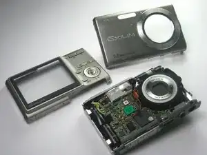
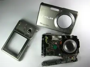
If you have experienced a decrease in the quality of sound, you may want to replace the speaker. This guide exposes the speaker for either investigation or replacement.

  1. Go3UTHnqtFg1STn3
    Go3UTHnqtFg1STn3
    VNWqB2EZZPEJYtPL
    QDcTWUcLCw1YGYuc
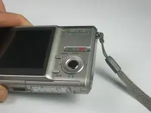
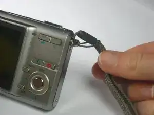
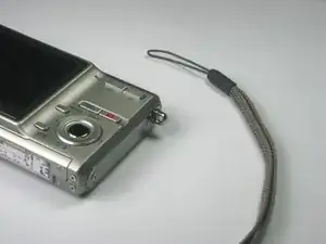
    • Remove the strap from the camera by pulling the thin cord out, creating a small loop, then pushing the thicker cord back through this loop.

  2. xPUKSRhmCuEfJQ2J
    xPUKSRhmCuEfJQ2J
    sPcVYqoXZUSTYI51
    4mEUiqwGiDMjtGvL
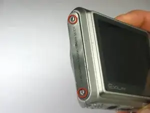
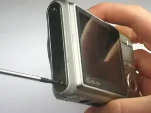
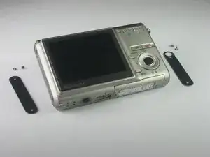
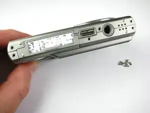
    • Remove the two Phillips screws (2.83 mm) from the left side panel of the camera casing.

    • The left panel can now be removed. However, one piece of tape attaches it to the camera, so a spudger may be required to ease the panels off.

    • Repeat for the right side panel of the camera.

    • Keep track of which screws go where. There are a couple sets of screws to take out and they are all small and look the same.

  3. JfP4r6ewmqCTGyMI
    JfP4r6ewmqCTGyMI
    kTPZCVMeAYG6IRVe
    RnOSaikEkStCqYFt
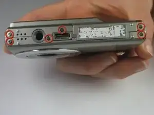
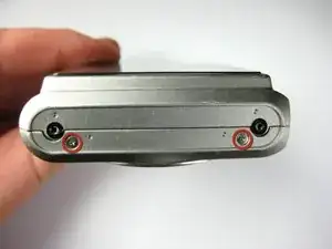
    • Remove the six Phillips screws (3.69 mm) from the bottom of the camera casing.

  4. GKGE14oSXFVbywvt
    GKGE14oSXFVbywvt
    v5rNVc65C1KgKRrD
    UummG5Gb2J2XBaLF
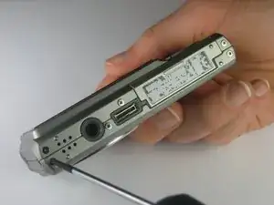
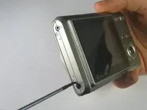
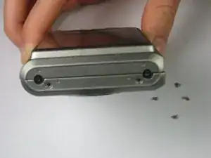
    • Remove the two Phillips screws (2.79 mm) on the left side of the camera where the metal panel used to be.

    • Repeat for the two Phillips screws (2.79 mm) right side of the camera.

  5. voFj5tPqUmBHXLU6
    voFj5tPqUmBHXLU6
    hkw1X5SlPgZauwdL
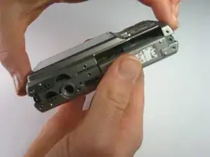
    • With the LCD screen facing up towards you, start at the bottom of the camera and gently pull off the back of the casing.

  6. TxYZwqbfIxcZrELf
    TxYZwqbfIxcZrELf
    lwWlmAXfmRR1lMyP
    qBkZQpTGuo2CMc2A
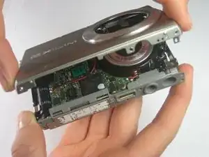
    • With the front side (with the lens) facing up towards you, start at the bottom of the camera and gently pull off the front of the casing.

    • The nob that previously held the camera strap will no longer be attached to the camera once you remove the camera casing. When putting the camera back together, remember to put the nob back into position before replacing the casing.

  7. WXHpHAC3meqfpkQ2
    WXHpHAC3meqfpkQ2
    qlb3HNBtfTIBnUBU
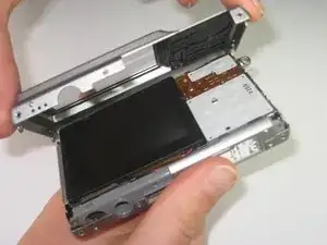
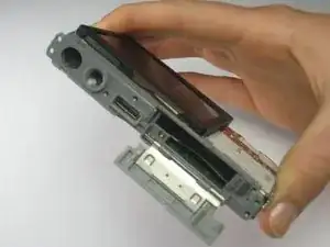
    • Slide the labeled piece toward the LCD screen and release.

    • The tab will spring open.

  8. YBVSmfRNGb1Dy4WU
    YBVSmfRNGb1Dy4WU
    JgPWCedMkiWk2els
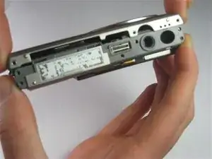
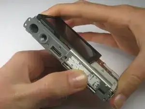
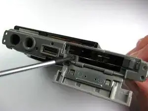
    • Look at the bottom of the camera. Take out the Phillips screw (1.77 mm) holding on the bottom plastic piece.

    • The bottom plastic piece is held on to the main frame of the camera only by two thin wires.

  9. cykuGGxFgmJrS1GW
    cykuGGxFgmJrS1GW
    sDFhVvPb6iHZo2JZ
    • The speaker is attached to the bottom of the camera casing with tape.

    • Use a spudger to gently peel the speaker away from the camera casing.

  10. HBhNVPjeTaVNiL1w
    HBhNVPjeTaVNiL1w
    C2Aktluof3NsxmAf
    ZilWWVoZ22IZxrBg
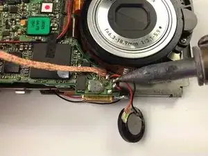
    • Using a soldering station and a solder wick or other solder removal tool, carefully remove the solder holding the two wires of the speaker to the circuit board.

    • There are two other soldering joints right next to the soldering joints for the speaker. These soldering joints are for the LCD screen only and should not be removed. Remove only the solder holding the speaker to the circuit board.

Conclusion

To reassemble your device, follow these instructions in reverse order.
Paul Fallon

Member since: 10/04/12

141 Reputation

0 comments