Introduction

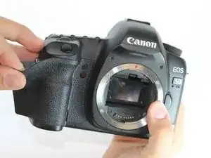
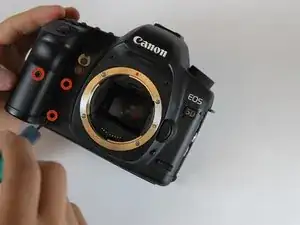
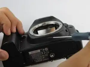
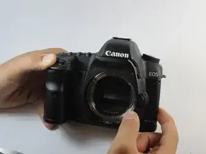
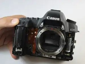
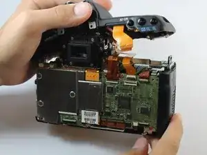
This guide will show users how to replace the top panel and access many internal parts such as the viewfinder and shutter assembly.

  1. 3aTQMjZErDDaHuAj
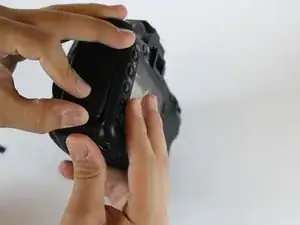
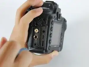
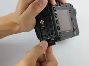
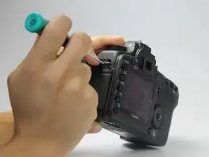
    • Lift the rubber flap covering the input/output jacks.

  2. ExhQMhD1ijZgwxQ1
    • Using a Phillips #000, remove the single 3.4 mm screw.

    You have gone this far, replace the battery anyway.

    I used a little blue tack to keep the screw in place

    Ron B -

  3. tHlTEK5BGFSBamET
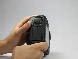
    • This step will permanently erase all user settings.

    • The memory battery can now be easily slid out of place.

    • If you are following this guide in an effort to perform a hard reset, you should now press the shutter button multiple times in order to drain any left over power, then replace the batteries and power the device back on. You have just performed a hard reset!

    In this step you also should remove the black screws to the left end right of the memory battery screw. Otherwise you can not remove the in/out port plastic covering in step 6.

    Per Feet -

  4. A5um5QnBoChAkGjG
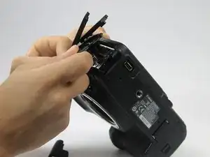
    • Peel back the rubber cover above the in/out ports to reveal two screw heads.

  5. yJraDyNfYahSnHCm
    • Remove both 5.4 mm screws using a Phillips #0.

    I just accidentally stripped one of those screws. Is there anything I can do or am I...screwed?

    Casey Ayers -

  6. 43i6cjhXN5AKZ1OH
    • Lift the in/out port plastic covering from the bottom where the backup battery used to be.

    Before removing the port cover, you must also remove the screw to the left of the mic jack and the screw below the HDMI port.

    Teovall -

  7. 2BWxE3lMBaUExfVV
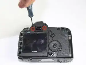
    • Remove each 6.3 mm screw on either side of the viewfinder using a Phillips #0 screwdriver.

    It is important to remove the diopter adjustment screw and the diopter wheel above the right screw. Otherwise you will not be able to take off the top panel in step 22.

    Per Feet -

    Use Phillips #00 screwdriver.

    Mr Blueeye -

  8. hALDcihdXSo1DF2a
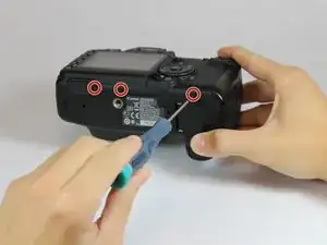
    • Remove the three 4.8 mm screws on the bottom of the back plate using a Phillips #0.

    The screw on the left side of this photo is shorter than the other two.

    rakurai -

  9. jQa4pIfbeHXPUKZt
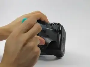
    • Peel back the rubber covering next to the menu dial to access the screw.

    • Remove the single 3.4 mm screw using a Phillips #0.

  10. lRaAjCR2kAxLpQ3R
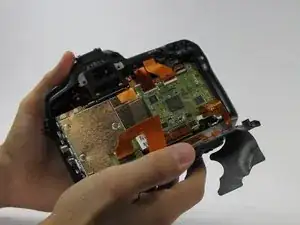
    • The back panel can now fall off easily by turning the device upside down. Be sure to catch it so the data ribbons do not tear or tug.

  11. UWkkLRibvmBEmkqb
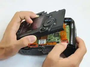
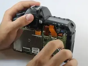
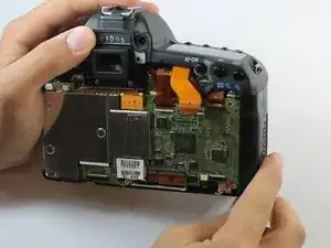
    • Remove each data ribbon cable from the motherboard by applying pressure down towards the motherboard and gently sliding your thumb upwards on the slot where the cable meets the motherboard. This will raise a very small clip that locks the cable in place.

    • The back panel is now free from the rest of the device.

  12. eXkph4sYVIH6cWkv
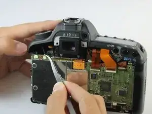
    • Using tweezers, pull out the wire attaching the front panel to the motherboard.

  13. EGkvlUhEeZWKiigG
    • Peel off the rubber cover on the front panel in order to access the screws underneath.

  14. 6ZTamgVHvhVEOYPw
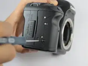
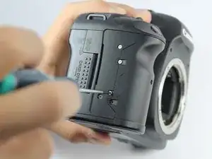
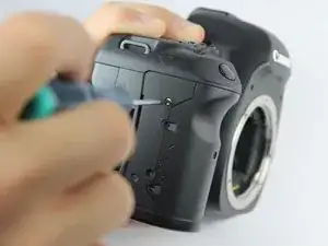
    • Remove each of the 4.9 mm three screws using a Phillips #0.

  15. 2N6HhICN3QudVNSK
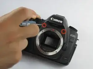
    • Remove the two 4.8 mm screws above where the lens would be using a Phillips #0.

  16. mKwJWSFmoUHjnHuH
    • Remove the single screw underneath where the lens would be using a Phillips #0.

  17. JxK32FY4BrkUxV22
    JxK32FY4BrkUxV22
    EPWgwbDyTn4MtE45
    YpdjkliahumMGSjG
    • Remove the four 3.0 mm screws next to the memory card reader using a Phillips #0.

  18. PeB2RBLv6SKx1KSF
    PeB2RBLv6SKx1KSF
    MtLdhv5KneiuOThv
    • Remove the front panel by lifting upwards from the right side where the in/out ports used to be.

    You need to remove the in/out port side panel first. There are two screws next to the mic in and below the HDMI out ports to remove.

    Radian -

  19. Q5MBcRph5ePN1DHo
    • Remove the single 5.9 mm screw next to the the strap loop on the same side as the shutter button.

  20. nLvhboAu5e1DP6KP
    • Remove the single 3.8 mm screw underneath the camera strap on the same side as the in/out ports.

    • If you are having problems finding this screw, note the orientation of the viewfinder in the bottom center of the photo.

  21. L3arvrNXeLGLwvib
    L3arvrNXeLGLwvib
    oM3DGt4HRgDvYrAO
    • Using tweezers or your thumb, raise the clasp holding the topmost data ribbon cable in order to release it.

  22. tuSpbKX6eJmqPmDN
    • The top panel is now free from the rest of the device. Lift to remove.

    You also need to remove the diopter adjustment wheel on the top right corner of the viewfinder.

    Radian -

Conclusion

To reassemble your device, follow these instructions in reverse order.

Mike Seed

Member since: 22/09/14

2983 Reputation

13 comments

The strap hook on the left side of my 5d2 body got bent in a fall and I want to replace it. Do I have to go through all these steps or is there an easier way to get to it ? Thanks

Tim -

Everything it's very nice in this guide.

I just have a question?

Where do I can find the top panel to buy it?

It's seem almost impossible...

stefano masetti -

I would also like to know where a replacement top panel can be purchased from.

t1000email -

I purchased one on Ebay , (US) $100 USD

yanhao996 -

The guide is useful and quite easy to follow. Thanks

Janes -
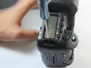
My EOS5Dii has a defective shutter button. It won't fire the shutter although, with the batter grip attached, the grip button is fine. Is accessing the button easy?

david -

I followed you tutorial to a tee and put on my camera new top cover. Now the camera is always on, even when the switch is off and no back buttons work, no image when shooting. The camera will shoot in off, middle and upper switch positions.

Top buttons - ISO, shutter speed work just fine. Auto focus is responsive. Aperture as well. Live View turns on but There is no image. Please advise if you have any idea what might have happened and what I could do to fix it. Thank you. Andrei

Andrei Rozen -

I opened the camera again and when I closed it, the date and time function came on . After that all camera functions and back buttons began working just fine, except one. The camera always stays on, regardless of on/off switch position, as long as the battery is inserted. Please advise, if you ever respond to messages in this discussion. Thank you.

Andrei Rozen -

Many thanks!! Managed to re-glue the light metering sensor which came off due to old age I guess.

However, I wasted 20 minutes as the guide doesn’t mention that in order to remove the top panel one must also remove the diopter adjustment knob.

Alexander Ivanchev -

Do you have to buy new rubber grip / tape or can you just press it on again?

Per Feet -

Good guide. Sucessfully replaced the top panel on my DSLR. Added a few comments in the instructions, because some screws that needed to be removed, were not described in the guide.

Per Feet -

Wow this was of help, I followed it and replaced my 5d mkiii mode dial, thanks alot

busulwa paddy -

These instructions are pretty good but as someone else commented: they do miss the diopter adjuster (which it appears you can remove at any time) and two screws in step 3. Recommend getting a #0 phillips screwdriver - these screws are easy to strip, The part # for top LCD is: canon CG2-2330-000 - on ebay for $43.

I highly recommend labeling which step your screws come from. There are no listed steps to replace the LCD part itself, so if I remember correctly there are 3 or 4 obvious screws you need to remove, unhook some ribbon cables, then you sort of gently lift twist and pull the panel and it will slide out (there is a little nub holding it in in the top left I think). I also recommend that after you get the display hooked back up you put a battery and memory card in it and test - my ribbon wasn’t seated properly and I had to disassemble and reseat,

Good luck! If you keep your screws sorted and use the right tools you should be able to do this in about 30-40 minutes if you move slow.

Darrin Rogers -